Compact broadband circular polarizer

A circular polarizer and compact technology, which is applied in the field of compact broadband circular polarizers, can solve problems such as the complexity of the circular polarizer feeding method, unfavorable system design and installation, and complex matching system design, and achieve the goal of feeding The method is simple and stable, the structure is simple, and the effect of broad application prospects

Active Publication Date: 2013-12-18
SHANGHAI JIAO TONG UNIV
View PDF4 Cites 13 Cited by
  • Summary
  • Abstract
  • Description
  • Claims
  • Application Information

AI Technical Summary

Problems solved by technology

According to the literature search of the existing technology, it is found that a circular polarizer widely used in the market is a square waveguide diaphragm circular polarizer HD-51.99SWSPS, but the feeding method of this circular polarizer is complicated and requires Three microwave ports, bulky, not conducive to system miniaturization
In the IEEE2011 International Symposium, Ilkyu Kim, YahyaRahmat-Samii and others proposed a circular polarizer in the article "Revisiting Stepped Septum Circular Polarizer Using Full-Wave Simulations". The circular polarizer is also large in size and In practical applications, it is necessary to design a complex matching system, which is not conducive to system design and installation

Method used


Image

  • Compact broadband circular polarizer
  • Compact broadband circular polarizer
  • Compact broadband circular polarizer

Examples


Embodiment Construction

[0033] The present invention will be described in detail below in conjunction with specific embodiments. The following examples will help those skilled in the art to further understand the present invention, but do not limit the present invention in any form. It should be noted that those skilled in the art can make several modifications and improvements without departing from the concept of the present invention. These all belong to the protection scope of the present invention.

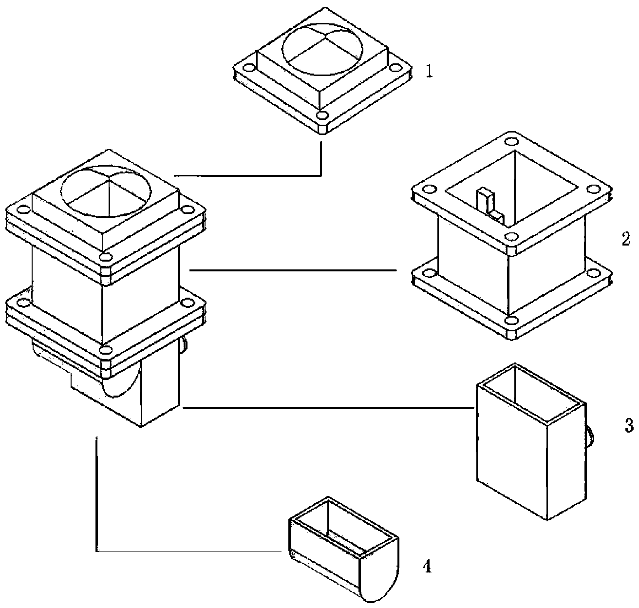
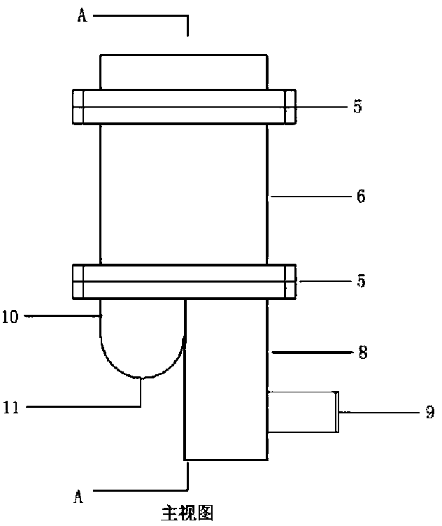
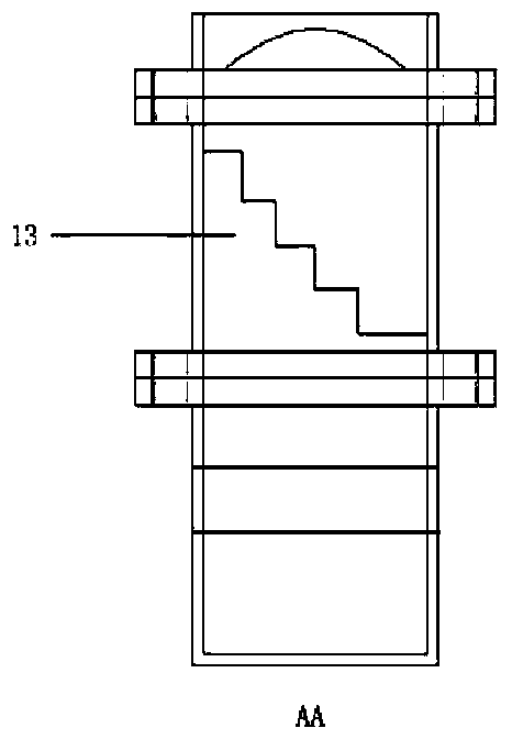
[0034] Please also see Figure 1 to Figure 7 , a compact broadband circular polarizer, including: a square-circle converter, a mode converter, a reflective back cavity and a feed source, the square-circle converter is connected to the upper end of the mode converter through a flange, and the reflective back cavity is connected to the feed source and Both are connected to the lower end of the mode converter through a flange.

[0035] Further, the square-circle converter is a cuboid transitioning f...


PUM


Abstract

The invention provides a compact broadband circular polarizer which comprises a square-circle converter, a mode converter, a reflecting back cavity and a feed source. The square-circle converter is connected to the upper end of the mode converter through a flange plate, and the reflecting back cavity and the feed source are connected and are connected to the lower end of the mode converter through the flange plate. The compact broadband circular polarizer is simple in structure, small in size, capable of covering wide frequency bands, capable of using the same circular polarizer for meeting the demands of mobile communications, satellite communications, short distance communications, broadband access communications and digital TV receiving with different standards in different areas, capable of meeting the demand for system miniaturization, and wide in application prospect.

Description

technical field [0001] The invention relates to a circular polarizer, in particular to a compact broadband circular polarizer based on a stepped partition and a reflective back cavity. Background technique [0002] With the development of modern communication, remote control, and telemetry technology, as well as the need for tracking and measurement of high-speed targets in various polarization modes and climatic conditions, a single linear polarization is easily affected, and polarization deterioration or polarization mismatch occurs. It is far from meeting the requirements of modern communication. Circularly polarized antennas can resist polarization deterioration and polarization mismatch very well, and show good advantages in harsh weather conditions such as clouds and rain and electronic interference environments, and are more sensitive and accurate in capturing violently shaking targets. There are many ways to implement circularly polarized antennas. The most common w...

Claims


Application Information

Patent Timeline
Patent Type & Authority Applications(China)
IPC IPC(8): H01Q15/24
Inventor 黄阳镇耿军平梁仙灵金荣洪白旭东
Owner SHANGHAI JIAO TONG UNIV
Why Eureka
Try Eureka