Pressure-limiting stop valve

A shut-off valve and pressure-limiting technology, applied in the field of pressure-limiting shut-off valves, can solve the problems of high water pressure of source water, hidden danger of pure water machine system, and increase of the cost of pure water machine system, so as to achieve easy installation and application and cost saving. Effect

Inactive Publication Date: 2010-09-15
高新区益腾净水设备研发中心
View PDF0 Cites 3 Cited by
  • Summary
  • Abstract
  • Description
  • Claims
  • Application Information

AI Technical Summary

Problems solved by technology

[0002] At present, the three-way valve or three-way joint of the pure water machine system only has the function of an ordinary three-way, and does not have the function of pressure limiting and filtering. The system causes potential safety hazards. The usual practice is to add a pressure limiting valve in the waterway to solve the problem of high source water pressure.
However, both the pressure reducing valve and the three-way valve are used in the pure water machine system, which increases the cost of accessories and installation required for the pure water machine system
On the other hand, the existing valves do not have a filtering function, so that the booster water shutoff pump with water shutoff function can only be installed after the first-stage filter unit of the pure water machine system, that is, the PP surface filter barrel, that is to say, the PP cotton filter The filter barrel is directly connected to the source water pipe network. When the source water pressure is high, the filter barrel has a greater pressure-bearing safety hazard; The combination of pressure cut-off valve and booster cut-off pump is a necessary and feasible solution to improve the safety performance of household water purifiers before installing the first-stage filter unit of the pure water machine, that is, the PP cotton filter barrel.

Method used


Image

  • Pressure-limiting stop valve
  • Pressure-limiting stop valve
  • Pressure-limiting stop valve

Examples


Embodiment Construction

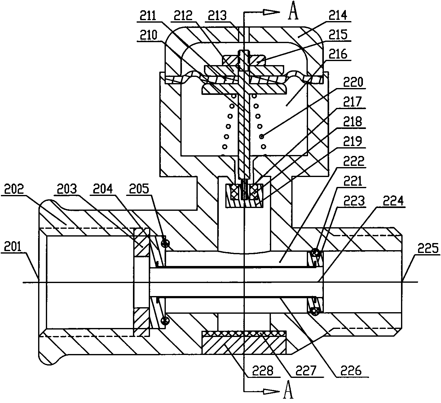
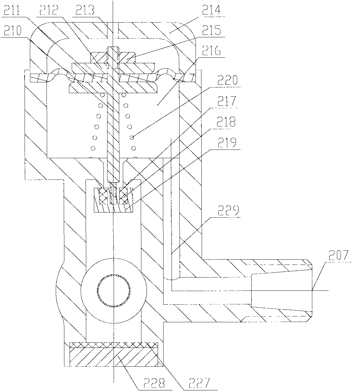
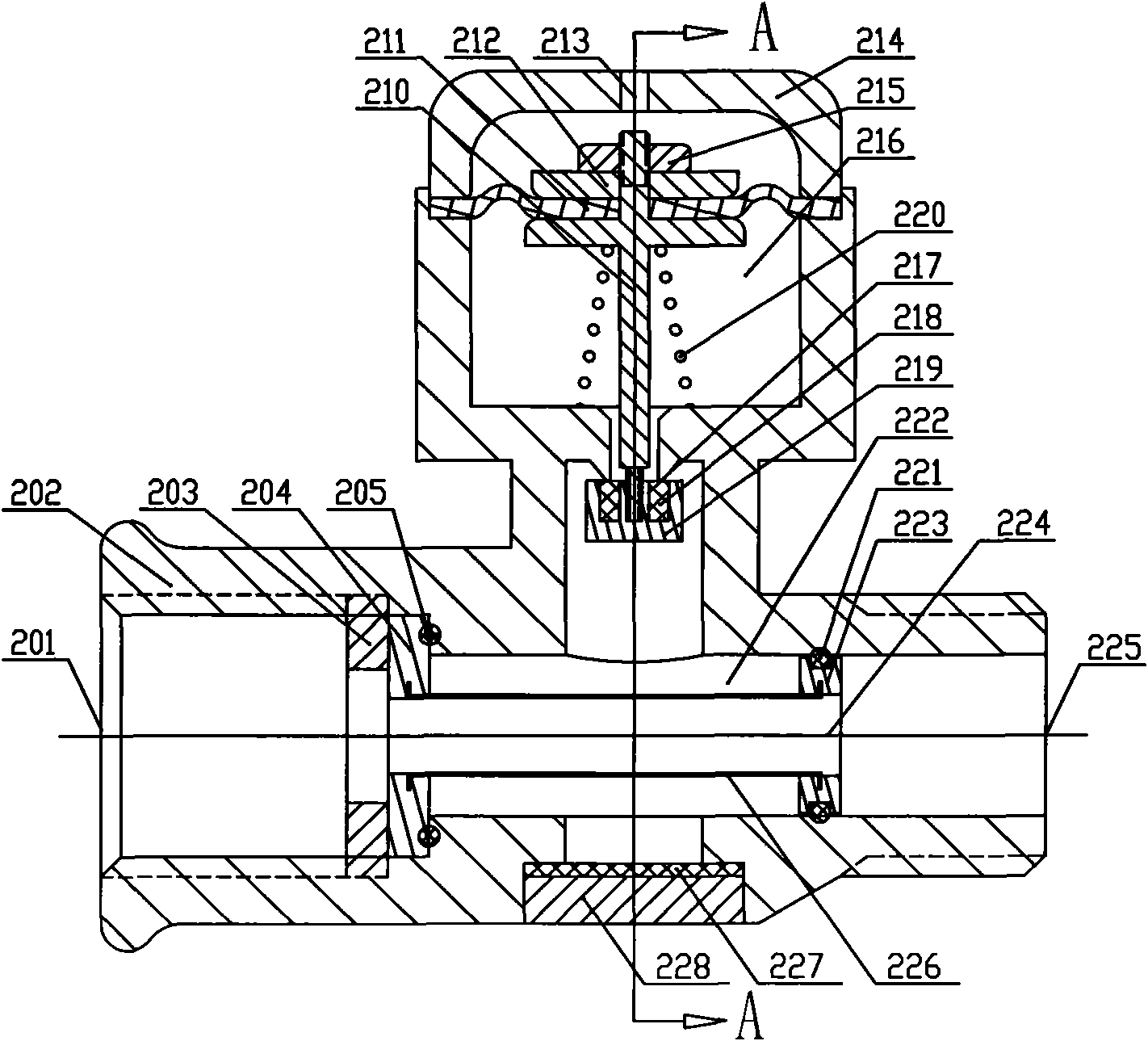
[0013] See Figure 1 to Figure 2 As shown, the pressure-limiting cut-off valve of the present invention includes a base 202. The base 202 has a source water inlet 225, a source water outlet 201, and a water purifier interface 207 that are connected to each other. The inlet 225 and the source water outlet 201 are connected with a pressure-limiting component; the source water inlet 225 and the source water outlet 201 are connected with a filter screen 226 with a hollow flow channel. The two ends of the filter screen 226 are respectively The rear ring seal 205 of the filter screen and the front ring seal ring 221 of the filter screen are sealed and fixed to the inner wall of the base 202; the filter screen 226 is cylindrical, and the hollow flow channel in it forms the source water channel 224. The watershed constitutes a filtered water cavity 222, the inlet end of the pressure limiting component is communicated with the filtered water cavity 222, and the outlet end of the pressur...


PUM


Abstract

The invention relates to a pressure-limiting stop valve. The pressure-limiting stop valve comprises a valve seat, wherein a source water inlet, a source water outlet and a filtered water outlet, which are communicated with one another, are formed in the valve seat; and a pressure-limiting component is arranged in a channel by which the filtered water outlet is communicated with the source water inlet and the source water outlet. The pressure-limiting stop valve is additionally provided with the pressure-limiting component in the channel by which the filtered water outlet is communicated with the source water inlet and the source water outlet; the pressure-limiting component can adopt a pressure-limiting structure similar to the pressure-limiting structure in the conventional water path pressure-limiting valve or pressure-reducing valve; and due to the adoption of the pressure-limiting component, the pressure of water flowing from the filtered water outlet through the pressure-limiting structure can be ensured to be in the set water pressure range so as not to cause potential safety hazard to a water purifier system. Compared with the conventional pressure-limiting valve or pressure-reducing valve arranged in front of a boosting water pump to serve as the pressure-limiting or pressure-reducing component independently, the pressure-limiting component of the scheme has the advantages of saving the valve seat of the pressure-limiting valve and cost, and conveniently installing and applying.

Description

Technical field [0001] The invention relates to a pressure limiting cut-off valve. Background technique [0002] At present, the three-way valve or three-way joint of the water purifier system only has the function of ordinary three-way, and does not have the function of pressure limiting and filtering. On the one hand, when the source water pressure is relatively high, the water purifier is usually The system poses a potential safety hazard. The usual practice is to add a pressure limiting valve in the waterway to solve the problem of high source water pressure. However, both the pressure reducing valve and the three-way valve are used in the pure water machine system, which increases the cost of accessories and installation required by the pure water machine system. On the other hand, the existing valve does not have a filtering function, so that the pressurized water cut-off pump with water cut-off function can only be installed after the first-stage filter unit of the pure w...

Claims


Application Information

Patent Timeline
Patent Type & Authority Applications(China)
IPC IPC(8): F16K17/04F16K51/00
Inventor 隆益腾
Owner 高新区益腾净水设备研发中心
Why Eureka
Try Eureka