Power supply system and power supply redundant control circuit thereof

A technology of redundant control and power supply, applied in circuit devices, emergency power supply arrangements, electrical components, etc., can solve the problems of unstable load power supply, load failure, multi-channel power failure, etc., and achieve the effect of solving unstable power supply

Active Publication Date: 2013-12-18
EVOC SMART IOT TECH CO LTD
View PDF3 Cites 32 Cited by
  • Summary
  • Abstract
  • Description
  • Claims
  • Application Information

AI Technical Summary

Problems solved by technology

[0006] The purpose of the present invention is to provide a redundant power supply control circuit, aiming to solve the problems in the prior art that the power supply to the load is unstable, it is easy to cause load failure, and it is easy to cause multiple power supply failures when the load is short-circuited.

Method used


Image

  • Power supply system and power supply redundant control circuit thereof
  • Power supply system and power supply redundant control circuit thereof
  • Power supply system and power supply redundant control circuit thereof

Examples


Embodiment 1

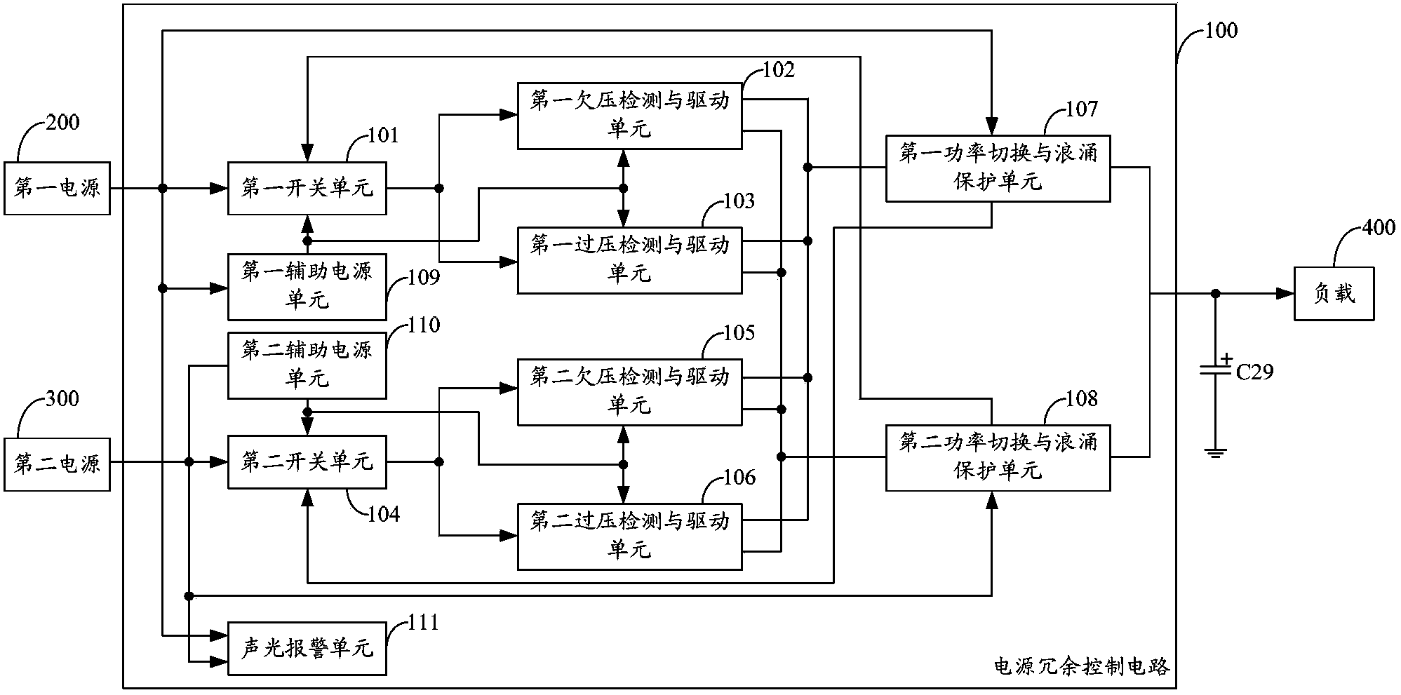
[0050] figure 1 It shows the module structure diagram of the redundant power supply control circuit provided by the first embodiment of the present invention. For the convenience of explanation, only the parts related to the first embodiment of the present invention are shown, and the details are as follows:

[0051] The redundant power supply control circuit 100 is connected to the first power supply 200, the second power supply 300 and the load 400, and the redundant power supply control circuit 100 includes:

[0052] First switch unit 101, first undervoltage detection and drive unit 102, first overvoltage detection and drive unit 103, second switch unit 104, second undervoltage detection and drive unit 105, second overvoltage detection and drive unit 106. The first power switching and surge protection unit 107 and the second power switching and surge protection unit 108;

[0053] The input end of the first switch unit 101 is connected to the output end of the first power s...

Embodiment 2

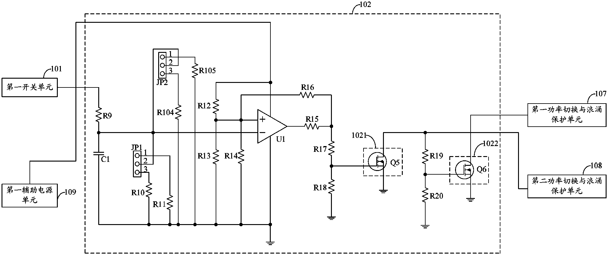
[0069] In this example, combined with Figure 2 to Figure 12 It should be understood that each component unit in the redundant power supply circuit is described, and this embodiment is only an illustration of one of the implementation modes of the present invention, and the details are as follows:

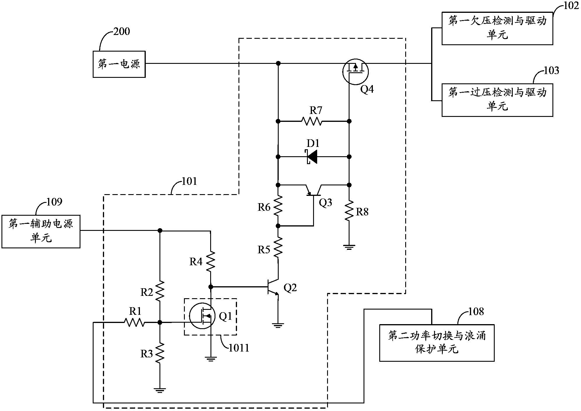
[0070] As an embodiment of the present invention, such as figure 2 As shown, the first switch unit 101 includes:

[0071] Resistor R1, resistor R2, resistor R3, resistor R4, first switch tube 1011, NPN transistor Q2, resistor R5, resistor R6, PNP transistor Q3, Schottky diode D1, resistor R7, PMOS transistor Q4 and resistor R8;

[0072]The first end of the resistor R1 is the sampling voltage input end of the first switch unit 101, and the second end of the resistor R1 is simultaneously connected with the first end of the resistor R2, the first end of the resistor R3 and the control end of the first switch tube 1011 , the second terminal of the resistor R2 is the power supply ter...

Embodiment 3

[0119] In this embodiment, the first auxiliary power supply unit 109 , the second auxiliary power supply unit 110 , and the sound and light alarm unit 111 have the same circuit structure as that provided in the second embodiment of the present invention, so details are not repeated here.

[0120] Combine the following Figure 13 to Figure 20 Each component unit in the redundant power supply control circuit provided by this embodiment is described. It should be understood that this embodiment is only an illustration of one of the implementation modes of the present invention, and the details are as follows:

[0121]In this embodiment, the first switch tube 1011 in the first switch unit 101, the second switch tube 1021 and the third switch tube 1022 in the first undervoltage detection and drive unit 102, the first overvoltage detection and drive unit The fourth switching tube 1031 and the fifth switching tube 1032 in 103, the sixth switching tube 1041 in the second switching uni...


PUM


Abstract

The invention provides a power system and a power supply redundant control circuit thereof, and relates to the field of power supply circuits. The power supply redundant control circuit comprises a first switch unit, a first undervoltage detection and drive unit, a first overvoltage detection and drive unit, a second switch unit, a second undervoltage detection and drive unit, a second overvoltage detection and drive unit, a first power switch and surge protection unit and a second power switch and surge protection unit. By means of the power supply redundant control circuit, real-time undervoltage and overvoltage detection is carried out on two power supplies, work state monitoring is carried out on an output stage, according to the work state of the two power supplies, seamless power supply switching is achieved so that a load can obtain stable power supply voltage and work normally, and the problems that in the prior art, power cannot be stably supplied to a load, load failure tends to occur, and when the load is short-circuit, failure of multiple power supplies tends to occur are solved.

Description

technical field [0001] The invention belongs to the field of power supply circuits, in particular to a power supply system and a power supply redundancy control circuit thereof. Background technique [0002] At present, in many power systems, in order to avoid the complete paralysis of the entire power system when one of the power sources fails, it is common to use power redundancy technology to configure the unfailed power source to replace the faulty power source to supply power to the load, so that the power system Can continue to maintain good working condition. [0003] The prior art provides a redundant power supply parallel circuit, which uses a MOS tube as a voltage detection point between the two power supply outputs and the load, and uses a control detection unit to monitor the voltage of the MOS tube after the body diode of the MOS tube is turned on. The drain-source voltage is detected in real time to determine whether the power supply of the branch is working n...

Claims


Application Information

Patent Timeline
Patent Type & Authority Applications(China)
IPC IPC(8): H02J9/06
Inventor 陈志列万小伟王志远
Owner EVOC SMART IOT TECH CO LTD
Why Eureka
Try Eureka