A second-order active filter circuit

A second-order active filter and circuit technology, which is applied in the field of filter circuits, can solve the problems of limited bandwidth of integrated operational amplifiers and inability to filter power signals, and achieve the effects of strong filtering ability, good stability, and simple circuit structure

Inactive Publication Date: 2016-06-08
昆山龙仕达电子材料有限公司
View PDF4 Cites 0 Cited by
  • Summary
  • Abstract
  • Description
  • Claims
  • Application Information

AI Technical Summary

Problems solved by technology

[0002] The main function of the filter is to transmit useful frequency components in the input signal. In engineering, it is usually used for signal processing, data transmission, and interference suppression. At present, the operating frequency of the filter circuit is very high, but due to the bandwidth of the integrated op amp Limited, unable to filter the power signal

Method used


Image

  • A second-order active filter circuit

Examples


Embodiment Construction

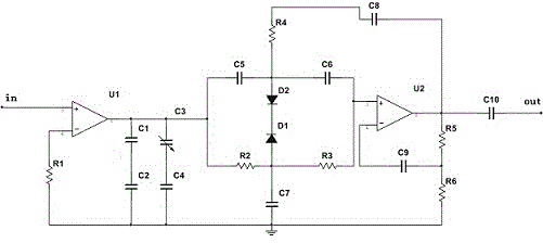
[0010] Such as figure 1 As shown, the present invention includes operational amplifiers, variable capacitors, capacitors, resistors and diodes. The non-inverting input terminal of the first operational amplifier U1 is used as a signal input terminal, and its inverting input terminal is grounded through the first resistor R1. The output terminal of the amplifier U1 is grounded through the series connection of the first capacitor C1 and the second capacitor C2. One end of the variable capacitor C3 is connected to the output terminal of the first operational amplifier U1, and the other end is grounded through the fourth capacitor C4. The first operational amplifier The output terminal of U1 is connected to the non-inverting input terminal of the second operational amplifier U2 through the series connection of the fifth capacitor C5 and the sixth capacitor C6, and the output terminal of the first operational amplifier U1 is connected through the series connection of the second resi...


PUM


Abstract

The invention discloses a second-order active filter circuit, which includes operational amplifiers, variable capacitors, capacitors, resistors and diodes. The invention uses band-stop filtering to suppress or attenuate signals in a certain frequency band, allowing All signals pass through, with strong anti-interference characteristics, simple circuit structure, good stability, and strong filtering ability.

Description

technical field [0001] The invention relates to a filter circuit, in particular to a second-order active filter circuit. Background technique [0002] The main function of the filter is to transmit useful frequency components in the input signal. In engineering, it is usually used for signal processing, data transmission, and interference suppression. At present, the operating frequency of the filter circuit is very high, but due to the bandwidth of the integrated op amp Limited, the power signal cannot be filtered. [0003] Therefore need a kind of new technical scheme to solve the above problem. Contents of the invention [0004] Purpose of the invention: In view of the problems and deficiencies in the above-mentioned prior art, the purpose of the invention is to provide a second-order active filter circuit, which can effectively suppress useless frequency components in the input signal. [0005] Technical solution: The technical solution adopted in the present inventi...

Claims


Application Information

Patent Timeline
Patent Type & Authority Patents(China)
IPC IPC(8): H03H11/46
Inventor 王火明
Owner 昆山龙仕达电子材料有限公司
Why Eureka
Try Eureka