

Sounding device for disposable guide type anorectal hemorrhoid anastomat
A guided anorectal hemorrhoid and sound-producing device technology, which is applied to surgical fixation nails and other directions, can solve the problems of high material requirements of the shim ring, low sound, inconspicuous sound, etc., and achieves the effect of convenient operation, reduced experience requirements, and loud sound.
- Summary
- Abstract
- Description
- Claims
- Application Information
AI Technical Summary
Problems solved by technology
Method used
Image

Examples
Embodiment Construction
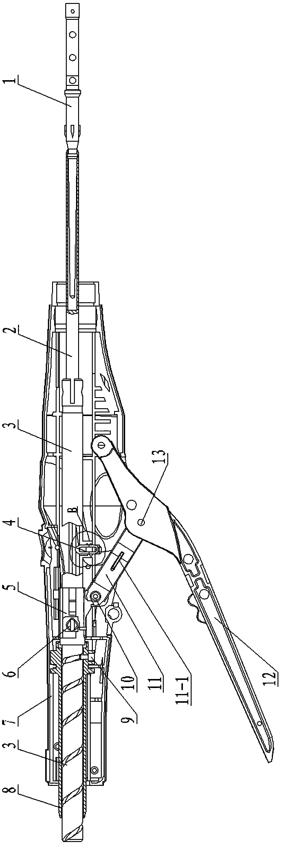
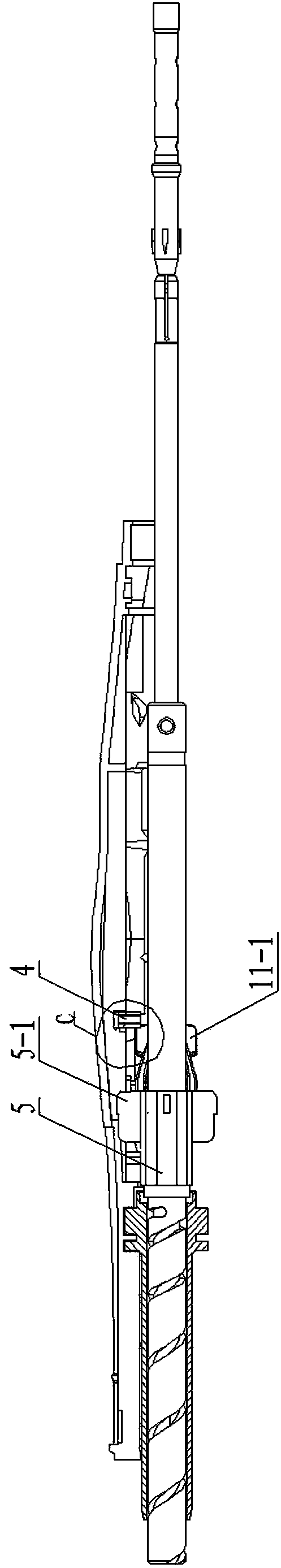
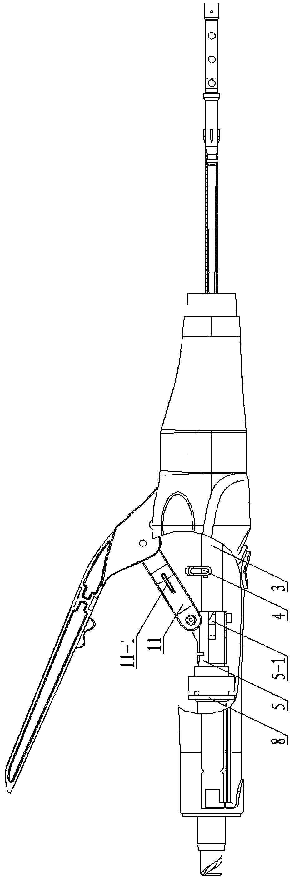
[0023] Refer to attached Figure 1-9 , Disposable guiding type anorectal hemorrhoid stapler sounding device includes sounding block 4, moving block 5, moving block 5, support rod 11, screw rod 3, movable handle 12 and fixed handle 7.
[0024] The sounding block 4 has a sounding block body 4-1, the sounding block body 4-1 is provided with a sounding chamber 4-2, and a rib 4-3 is arranged on one side of the sounding block body 4-1, and a sounding block body 4-1 One end is provided with an arc-shaped protrusion 4-4, and the other end of the sounding block body 4-1 is provided with a top block 4-5.
[0025] The middle part of the fixed handle 7 is provided with a sounding block installation groove 7-1, and in the sound block installation groove 7-1, a convex rib mobile positioning groove 1 7-2 and a convex rib mobile positioning groove 2 7-3 are arranged.
[0026] The moving block 5 is provided with a screw mounting hole 5 - 1 , and a wedge 5 - 2 is provided on one side of the mo...
PUM
 Abstract
Description
Claims
Application Information