Jetting glue dispensing valve device and jetting glue dispensing method

A spray point and glue valve technology, which is applied to devices and coatings that apply liquid to the surface, can solve the problems of inconsistent volume of sprayed glue, decreased packaging quality, and difficulty in spraying large-viscosity glue, and achieves motion symmetry. And the effect of uniform, uniform and tidy movement, and symmetrical, uniform and tidy glue movement

Inactive Publication Date: 2013-12-25
CENT SOUTH UNIV
View PDF5 Cites 19 Cited by
  • Summary
  • Abstract
  • Description
  • Claims
  • Application Information

AI Technical Summary

Problems solved by technology

[0004] The invention provides a jet dispensing valve device and a jet dispensing method, the purpose of which is to set a turntable with holes in the glue supply valve and drive the turntable to rotate through a transmission gear to overcome the problems in the prior art. In the continuous working process, there are problems such as inconsistency in the volume of sprayed glue, difficulty in spraying high-viscosity glue, and precipitation of fluorescent powder in the glue, which leads to the decline in the quality of subsequent packaging.

Method used


Image

  • Jetting glue dispensing valve device and jetting glue dispensing method
  • Jetting glue dispensing valve device and jetting glue dispensing method
  • Jetting glue dispensing valve device and jetting glue dispensing method

Examples


Embodiment Construction

[0031] The present invention will be further described below in conjunction with the accompanying drawings and embodiments.

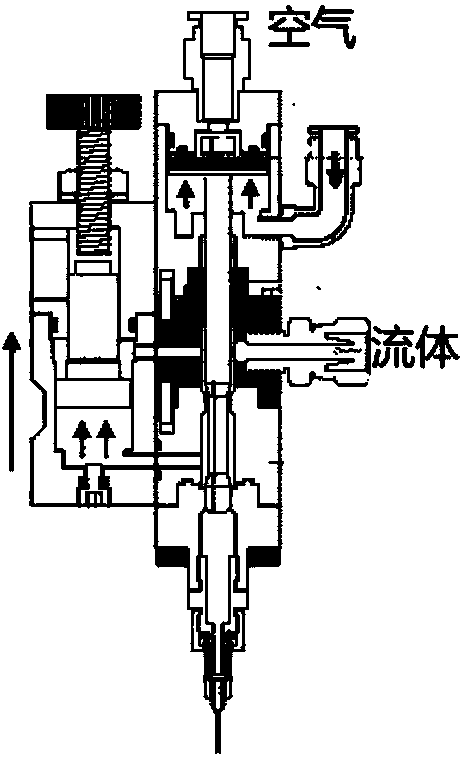
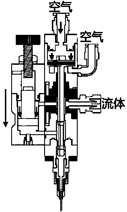
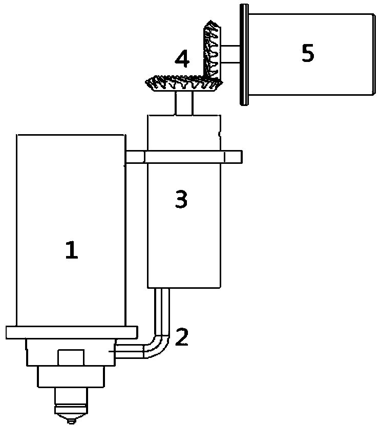
[0032] Such as image 3 and Figure 4 As shown, it is a schematic diagram of the device structure of the present invention, a jet dispensing valve device, including a jet dispensing valve main body 1, a glue supply valve 3 and a glue supply pipeline 2, and the jet dispensing valve main body 1 is provided with a tail end Connect the striker 10 of the spring 6 and the first air supply hole 7 that inflates the injection dispensing valve cavity 8 from the outside; the glue supply valve 3 is provided with a second air supply hole 14 that inflates the glue supply valve cavity 13 from the outside, and the injection point The glue valve cavity 8 communicates with the glue supply valve 3 through the glue supply pipeline 2; it is characterized in that it also includes a transmission gear 4, a drive motor 5 and a turntable 12 arranged inside the glue supply valve...


PUM


Abstract

The invention discloses a jetting glue dispensing valve device and a jetting glue dispensing method. The jetting glue dispensing valve device comprises a jetting glue dispensing valve, a glue supply pipeline and a glue supply valve, wherein a turntable capable of being closed / opened quickly is mounted at the bottom of the glue supply valve. During a glue jetting course, the glue supply valve is closed, and a channel allowing a glue solution to flow back to the glue supply valve from the glue supply pipeline is intercepted, so that glue jetting with precise volume is achieved. After a single glue jetting course is finished, the glue supply valve is opened, and the glue supply channel is opened for filling, so that continuous jetting of the glue solution is achieved. When the device and the jetting glue dispensing method are used for glue dispensing, no backflow occurs, so that an effective utilization rate of striker movement is increased, and jetting of a high-viscosity glue solution is facilitated; the device is simple in structure and easy to process; the turntable has the characteristic of periodic rotation, and can stir the glue solution, so that precipitation of fluorescent powder in the glue solution is avoided effectively; the fluid velocity in the jetting glue dispensing valve is distributed more uniformly; and the glue dispensing quality is ensured.

Description

technical field [0001] The invention relates to a jet dispensing valve device and a jet dispensing method. Background technique [0002] Jet dispensing is one of the key technologies in microelectronic packaging, especially in LED and wire-bond packaging. In today's highly competitive electronic packaging market, there are mainly three widely used contact dispensing methods, namely time-pressure type, screw pump type and piston-valve type. However, as fierce competition in microelectronic packaging forces microelectronic packaging to develop towards higher density, smaller size and faster speed, traditional contact glue spraying can no longer meet the requirements of modern packaging. Contact dispensing is too inefficient, and modern packaging requires dispensing speeds in excess of 45,000 dots / hour. In addition, since the size of the package is getting smaller and smaller, the contact glue dispensing valve cannot enter the narrow space in the chip to complete the dispensi...

Claims


Application Information

Patent Timeline
Patent Type & Authority Applications(China)
IPC IPC(8): B05C11/10B05C5/02
Inventor 李涵雄陈云王福亮
Owner CENT SOUTH UNIV
Why Eureka
Try Eureka