Electric or pneumatic continuous syringe

A syringe and electric drive technology, applied in veterinary instruments, medical science, etc., can solve the problems of continuous injection without better design and modification, and achieve the effect of improving injection accuracy and reducing injection fatigue.

Pending Publication Date: 2019-03-29
CAINA TECH CO LTD
View PDF2 Cites 0 Cited by
  • Summary
  • Abstract
  • Description
  • Claims
  • Application Information

AI Technical Summary

Problems solved by technology

It is all about the continuous injection of doses, and there is no better design and change for continuous injection

Method used


Image

  • Electric or pneumatic continuous syringe
  • Electric or pneumatic continuous syringe
  • Electric or pneumatic continuous syringe

Examples


Embodiment 1

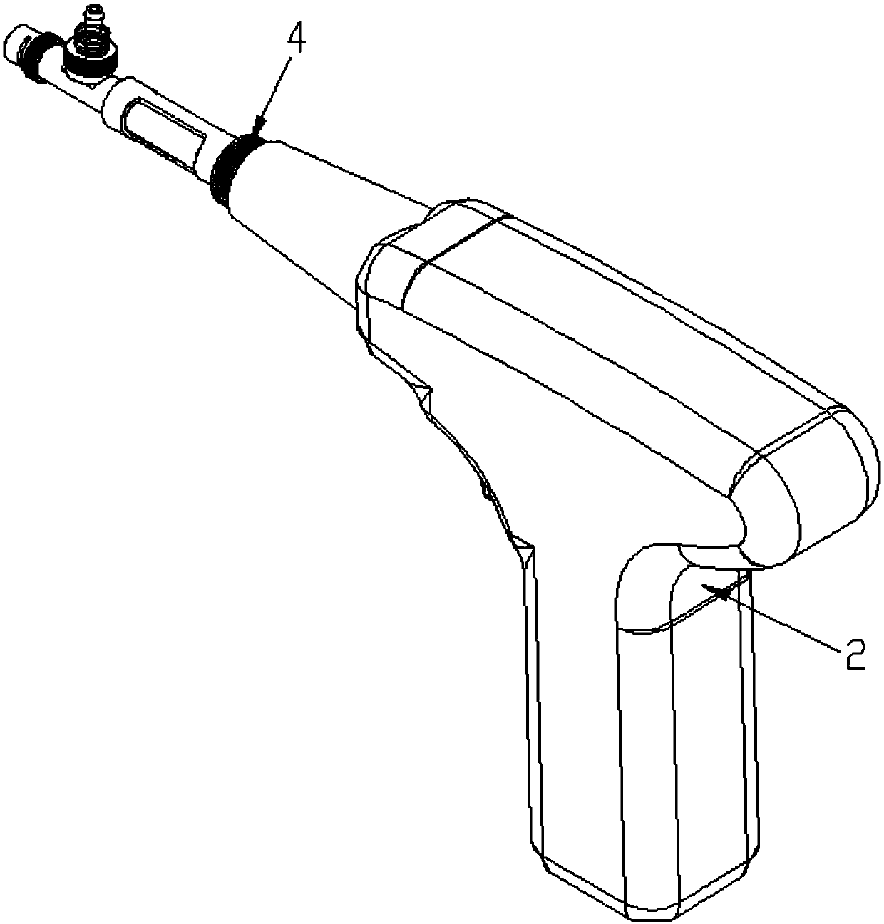
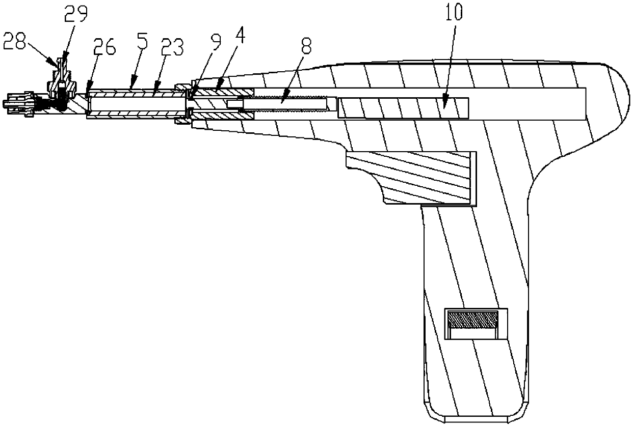
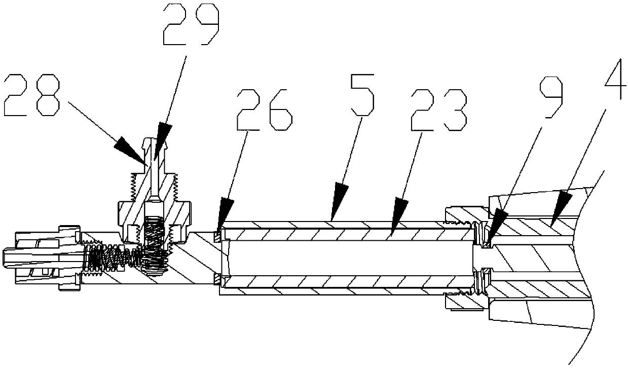
[0038] Such as Figure 1 to Figure 13 shown (for ease of illustration, Figure 1 to Figure 11All parts of the push rod drive mechanism are not shown, only the movable rod 10 inside is shown), the present invention is an electric or pneumatic continuous injector, including a handle 2 provided with a grip end 1, and the handle 2 also includes two A cavity 3 that runs through the handle 2 is provided between the opposite end and the two ends, and one end of the connecting shaft 4 of the push rod sleeve is arranged in the cavity 3, and the liquid medicine cartridge 5 is connected with the push rod sleeve through the connection structure 6 The other end of the shaft 4 is detachably connected, the liquid pumping port 7 is set on the liquid medicine cylinder 5, the push rod 8 is slid inside the liquid medicine cylinder 5, the piston 9 is set at one end of the push rod 8, and the other end of the push rod 8 is connected with the push rod The movable rod 10 of driving mechanism is fix...

Embodiment 2

[0040] The difference from Embodiment 1 is that, as Figure 14 As shown, the electric driving part includes a servo motor 20 arranged on the bottom wall of the cavity 3, the motor shaft of the servo motor 20 is connected with the gear 21 through a reducer, and the part facing the bottom wall of the cavity 3 on the movable rod 10 is connected with the gear 21. meshing racks.

Embodiment 3

[0042] The difference from Embodiment 1 is that, as Figure 15 As shown, the electric driving part includes a servo motor 20, and the servo motor 20 is arranged in the cavity 3 of the T-shaped handle. One side of the segment is in rolling connection with the friction wheel 37, and the other side of the friction segment is in rolling connection with the driven wheel 38, and the driven wheel 38 is connected with the housing of the T-shaped handle through a pin shaft.


PUM


Abstract

The invention discloses an electric or pneumatic continuous syringe. The syringe comprises a T-shaped handle, wherein a penetrating through hole is formed in the handle; a ladder-shaped sleeve is arranged at one end of the through hole, the small-sized end of the sleeve is arranged in the through hole, a medicinal liquid cylinder is detachably connected with big-sized end of the sleeve through a connecting structure; a push rod is arranged on the medicinal liquid cylinder in a sliding manner; the other end of the push rod is fixedly connected with a movable rod of a push rod driving mechanism;the push rod driving mechanism comprises a cylinder and a movable rod, and two ends of the movable rod extend out of the cylinder; a piston is arranged in the middle of the movable rod; two sides ofthe piston on the cylinder are respectively connected one end of each air pipe, and the other end of each air pipe is respectively connected with the P opening and T opening of a three-position four-way directional control valve or two-position four-way directional control valve; holes to be penetrated by the two air pipes are formed in the shell of the handle; and the A opening and B opening of the three-position four-way directional control valve or two-position four-way directional control valve are respectively connected with an exhaust pipe and an air pump. The electric or pneumatic continuous syringe can be used for continuously injecting medicines by adopting pneumatic driving or electric driving, so that the injection fatigue can be reduced, and the injection accuracy can be improved.

Description

technical field [0001] The invention relates to an electric or pneumatic continuous injector. Background technique [0002] Most of the current syringes use manual methods, which are prone to fatigue when too many injections are made. The authorized notification number is CN105997290 B patent: a step-by-step continuous syringe, which includes a cylinder and a piston rod. The end of the piston rod is connected to a piston. The piston is located in the cylinder. A liquid bottle fixer is connected to the top, and an adjustment device is connected to the cylinder body. The adjustment device includes a hollow shell and a positioning pin. A dispatching disc is installed in the housing. The dispatching disc includes a fixing part and a positioning part. The fixing part includes buckles and The positioning ring, the snap button and the positioning ring are the same as the fixed scheduling disc, the positioning part includes a positioning groove and a gear groove, the positioning pi...

Claims


Application Information

Patent Timeline
Patent Type & Authority Applications(China)
IPC IPC(8): A61D7/00
CPCA61D7/00
Inventor 陆军赵丽杰倪琳
Owner CAINA TECH CO LTD
Why Eureka
Try Eureka