Double-end jaw-type wheel pair withdrawal machine

A claw-type, unloading machine technology, applied in the direction of wheels, tire installation, tire parts, etc., can solve the problems of insufficient rigidity, poor accuracy, and high requirements for press-fitting accuracy

Active Publication Date: 2013-12-25
HUBEI HEQIANG MACHINERY DEV LIMITED BY SHARE
View PDF5 Cites 3 Cited by
  • Summary
  • Abstract
  • Description
  • Claims
  • Application Information

AI Technical Summary

Problems solved by technology

[0002] With the speed increase of trains, especially in recent years, in order to adapt to the rapid development of the railway freight transportation market, the speed increase of freight trains and the construction of high-speed railways, and the operation of high-speed electric locomotives with a speed of 200km / h have changed from the previous axle-holding boxes to To meet the needs of stable, safe and reliable high-speed transportation, the emergence of special wheel sets with high-power motors, gearboxes, 2 to 3 brake discs, imported wheelsets, etc., brings various high-precision wheel sets for pressing and unloading And the amount of maintenance is increasing, and the precision of press-fitting is high, the difficulty of unloading and maintenance is high, and the quality of unloading is improved. The wheels, brake discs, gears, gearboxes and The pressing and dismounting of special wheel sets not only has poor precision, low efficiency, high noise, and high labor intensity, but also has poor quality of pressing and dismounting, and is unsafe, especially for high-speed electric locomotives with gearboxes and high-power motors. , 2 to 3 brake discs, because the gap between the wheel set and the gearbox is too small or even close, the insert plate or disassembly head of the existing wheel set unloading machine cannot enter it, so that the wheel set cannot be unloaded at all
For this reason, the applicant has applied for a patent for a wheel set pressure detection and unloading machine, which solves the above problems, but it is still not ideal. The workpiece needs to be rotated to complete the unloading during the working process, which delays time and affects efficiency, and the rigidity appears. insufficient

Method used


Image

  • Double-end jaw-type wheel pair withdrawal machine
  • Double-end jaw-type wheel pair withdrawal machine
  • Double-end jaw-type wheel pair withdrawal machine

Examples


Embodiment Construction

[0013] The present invention will be further described below in conjunction with the accompanying drawings.

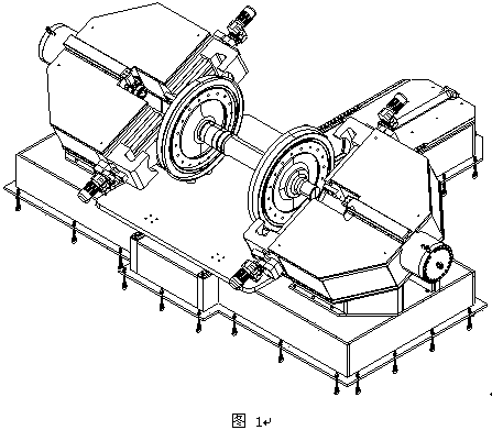
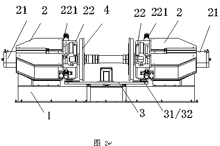
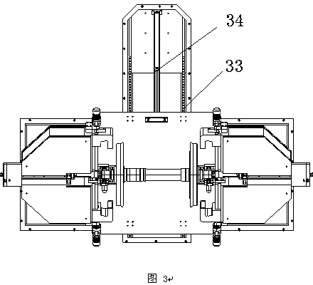
[0014] Such as Figure 1 to Figure 4 As shown, the present invention discloses a double-head jaw type wheel set unloading machine, which includes a base 1, left and right heads 2, left and right main oil cylinders 21, a workbench 3, a detection system, a hydraulic system, an electrical Control system, the two ends of the base are respectively equipped with U-shaped machine heads 2, and they are inclined at a certain angle to facilitate the entry and exit of workpieces; the main oil cylinder is installed in the middle of the U-shape, and claw mechanisms are provided at both ends of the U-shape, and the two sides of the U-shape are respectively An opening and closing drive device 221 is provided. During work, the wheels are held by the claws, and the main oil cylinder withstands the wheel shaft, and the wheels can be retracted; the base is provided with a workbench 3, an...


PUM


Abstract

The invention relates to a double-end jaw-type wheel pair withdrawal machine which comprises a base, a left handpiece, a right handpiece, a left main oil cylinder, a right main oil cylinder, a workbench, a detection system, a hydraulic system and an electric control system; both ends of the base are respectively provided with U-shaped handpieces which are oblique for a certain angle; the main oil cylinders are arranged in the middle of the U shapes, jaw mechanisms are arranged on both ends of the U shapes, and opening and closing driving devices are respectively arranged on both sides of the U shapes; the workbench is arranged on the base; a guide rail and an in and out driving device are arranged below the workbench; roller frames are arranged on both ends above the workbench, and a linear guide rail is arranged below the workbench. The double-end jaw-type wheel pair withdrawal machine has the beneficial effects that the withdrawal is realized by clamping a wheel pair through jaws, so that the problem of an existing withdrawal machine that the withdrawal cannot be realized because the wheel pair is close to a case is solved; the structure is simple and reasonable, the handpieces are arranged obliquely, not only is the height of the whole machine reduced but also a work piece goes in and out conveniently, and is free from interference; the handpieces are fixed, and the rigidity strength is good; the double-end oil cylinders work, so that the machine withdraws without turning around, and the working efficiency is high.

Description

technical field [0001] The invention relates to equipment machinery for railway locomotives, in particular to a double-head jaw type wheel set unloading machine. It is suitable for unloading and pressure inspection of wheels, axles, brake discs, gears, etc. . Background technique [0002] With the speed increase of trains, especially in recent years, in order to adapt to the rapid development of the railway freight transportation market, the speed increase of freight trains and the construction of high-speed railways, and the operation of high-speed electric locomotives with a speed of 200km / h have changed from the previous axle-holding boxes to To meet the needs of stable, safe and reliable high-speed transportation, the emergence of special wheel sets with high-power motors, gearboxes, 2 to 3 brake discs, imported wheelsets, etc., brings various high-precision wheel sets for pressing and unloading. And the amount of maintenance is increasing, and the precision of press-f...

Claims


Application Information

Patent Timeline
Patent Type & Authority Applications(China)
IPC IPC(8): B60B29/00B23P19/027
Inventor 喻国锋范鸿童俊军张霄喻侃童光董婷婷吕志刚李昌齐
Owner HUBEI HEQIANG MACHINERY DEV LIMITED BY SHARE
Why Eureka
Try Eureka