High-precision anhydrous micro-leakage detection device

A leak detection device, high-precision technology, applied in the direction of liquid tightness measurement using liquid/vacuum degree, by measuring the increase and deceleration rate of fluid, etc., can solve the impact of air tightness detection, affect the mental state of work, and cumbersome operation and other problems, to achieve the effect of accurate and precise air tightness detection, improve detection accuracy, and high detection accuracy

Active Publication Date: 2016-04-20
ZHEJIANG VALOGIN TECH
View PDF5 Cites 0 Cited by
  • Summary
  • Abstract
  • Description
  • Claims
  • Application Information

AI Technical Summary

Problems solved by technology

[0003] The above-mentioned technology has the following disadvantages: 1. The detection device needs to be placed in water for detection. If things go on like this, there will be residual or leaked oil in the water during the mechanical detection process. The operator puts his hand in the water for a long time, which will cause the operator The skin of the hand is infected or even causes disease, which affects the health of the operator; 2. During the whole process of detection, the operation is relatively complicated. In the process from internal air tightness detection to external air tightness detection, it is necessary to Manually operating the on-off of the internal ventilation of the piece to be tested is a waste of time and energy, and at the same time the operation is very cumbersome; If air bubbles emerge from the air hole of the fixed joint, the internal airtightness is faulty. If air bubbles emerge from the part to be tested, the external airtightness is faulty. However, in the process of manual operation, it is easy to The generation of air bubbles has brought some unnecessary effects to the air tightness test, and it is easy to make false judgments. Similarly, if the operator stares at the water surface for a long time, the damage to the eyes will be greater and it will easily cause eye fatigue. , affect the mental state of work

Method used


Image

  • High-precision anhydrous micro-leakage detection device
  • High-precision anhydrous micro-leakage detection device
  • High-precision anhydrous micro-leakage detection device

Examples


Embodiment Construction

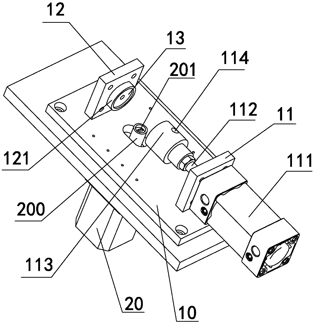
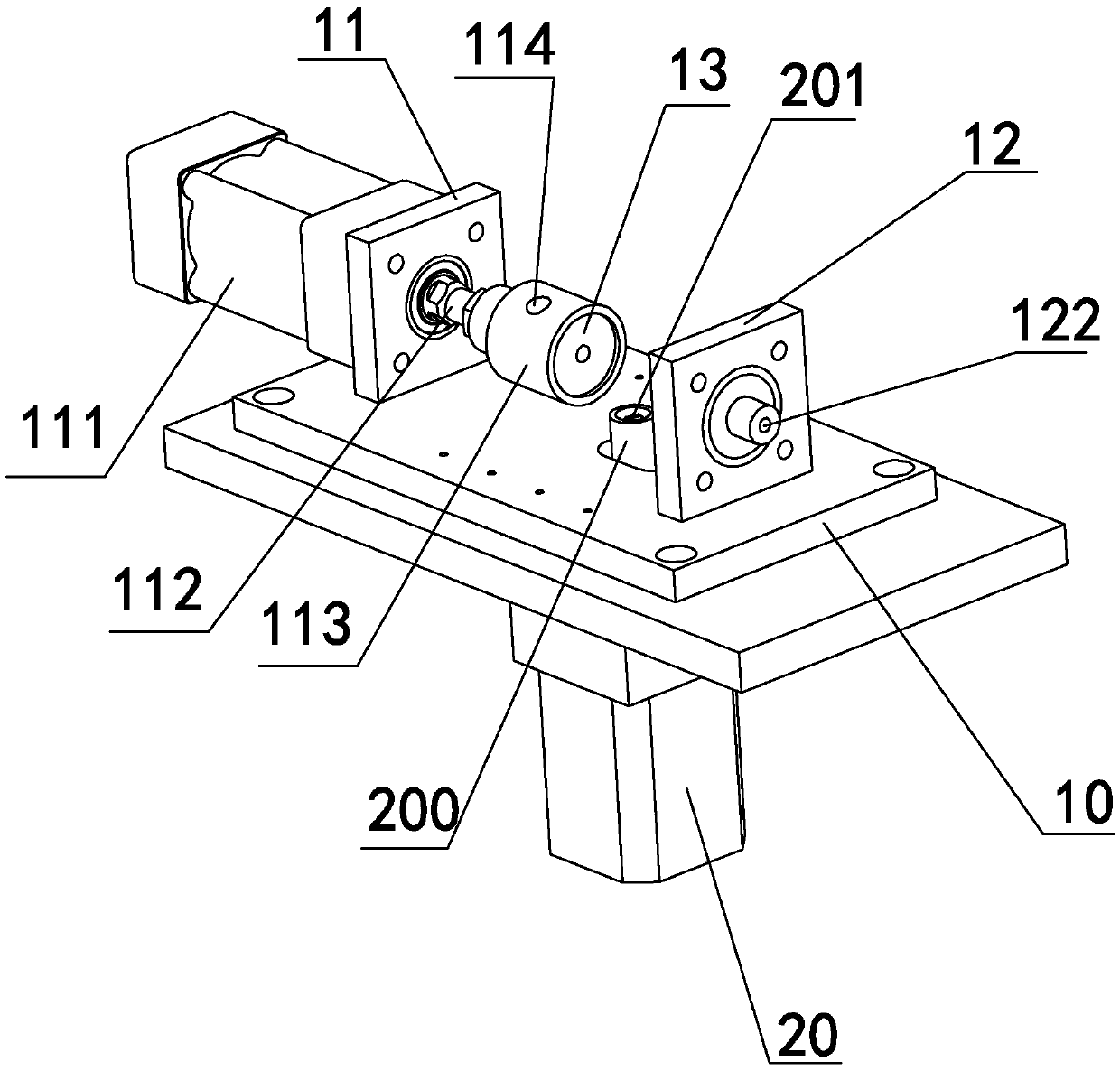
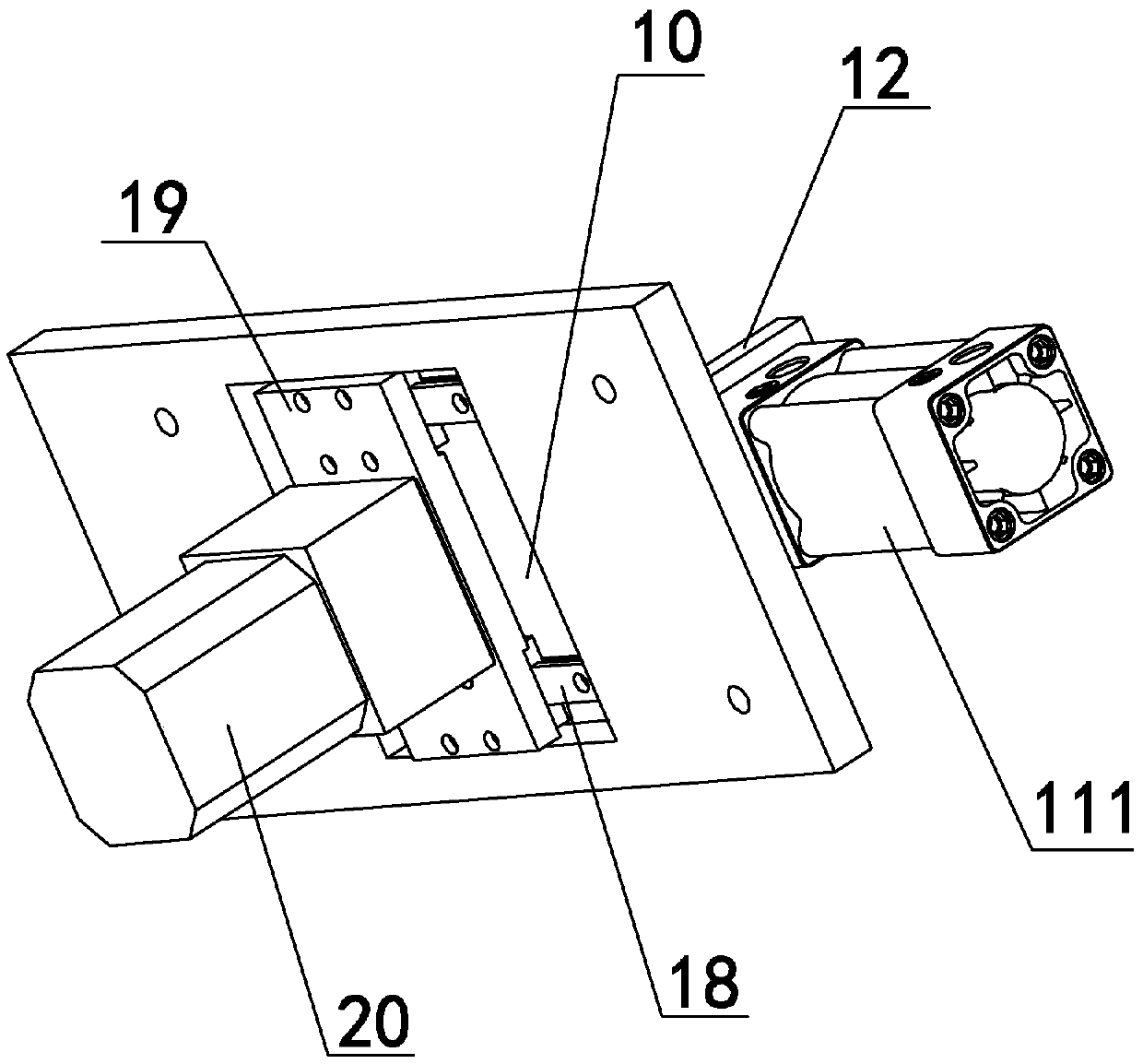
[0025] Such as Figure 1-4 As shown, it is a high-precision anhydrous micro-leakage detection device disclosed in the present invention. The substrate 10 is provided with a clamping mechanism, and the clamping mechanism is provided with an inflation hole 114 and a vent hole 122 that can be used to inflate and exhaust the object to be detected. The inflation hole 114 and the deflation hole 122 are respectively connected with an air path detection and control mechanism for controlling inflation, deflation and detection of air pressure difference, and an auxiliary knob mechanism is provided on one side of the clamping mechanism.

[0026] Such as Figure 1-3 As shown, the specific structure of the clamping mechanism is: one side on the front of the substrate 10 is fixed with a main vertical board 11, and the other side is fixed with a secondary vertical board 12, and the main vertical board 11 and the secondary vertical board 12 are arranged oppositely, and There is a certain int...


PUM


Abstract

The invention relates to the technical field of leakage detection devices, in particular to a high-precision water-free micro-leakage detection device used for detecting gas tightness of a valve. A clamping mechanism is arranged on a base plate, an air inflation hole and an air leakage hole are formed in the clamping mechanism, the air inflation hole is used for inflating air in a piece to be detected, and the air leakage hole is used for discharging the air from the piece to be detected, the air inflation hole and the air leakage hole are respectively connected with an air channel detection control mechanism for controlling air inflation and air discharging and detecting the pressure difference, and an auxiliary rotary knob mechanism is arranged on one side of the clamping mechanism. The high-precision water-free micro-leakage detection device has the advantages of being convenient to operate, high in detection precision and high in working efficiency, saving time and labor, and having certain guarantees to body health of operators.

Description

technical field [0001] The invention relates to the technical field of leakage detection devices, in particular to a high-precision anhydrous micro-leakage detection device for detecting the air tightness of valves. Background technique [0002] After the valve is manufactured, in order to ensure the quality and performance of the product, it is necessary to test the air tightness of the valve. Therefore, testing the air tightness of the valve is a very necessary link in the industry of manufacturing valves. At present, the traditional air-tightness testing device is equipped with a propulsion cylinder on one side of the substrate, and the end of the piston rod of the propulsion cylinder is equipped with a main joint with an air-filling hole. The air-filling hole is connected to an air pump, and the other side is provided with a fixed joint. , there are air holes on the fixed joint, and then the above-mentioned mechanism is placed in the water tank. When testing the air tig...

Claims


Application Information

Patent Timeline
Patent Type & Authority Patents(China)
IPC IPC(8): G01M3/28
Inventor 戴美云田保国张凤萍吴金贵
Owner ZHEJIANG VALOGIN TECH
Why Eureka
Try Eureka