Unlock instant, AI-driven research and patent intelligence for your innovation.

Method for determining uplink transmission interruption time, and equipment

A technology of transmission interruption and determination method, applied in the field of communication, can solve problems such as no solution

Active Publication Date: 2013-12-25
DATANG MOBILE COMM EQUIP CO LTD
View PDF6 Cites 8 Cited by
  • Summary
  • Abstract
  • Description
  • Claims
  • Application Information

AI Technical Summary

Problems solved by technology

[0014] In LTE-A R11 and later systems, the UE is allowed to aggregate cells with different duplex modes or different TDD UL / DL configurations. Therefore, the uplink transmission interruption time caused by the measurement gap may be different for all cells aggregated by the UE. Once it occurs If the uplink transmission interruption caused by the measurement gap, how should the UE stop the uplink transmission on each cell, there is no solution to this problem in the prior art

Method used


Image

  • Method for determining uplink transmission interruption time, and equipment
  • Method for determining uplink transmission interruption time, and equipment
  • Method for determining uplink transmission interruption time, and equipment

Examples


Embodiment 1

[0042] Embodiment 1 of the present invention provides a method for determining uplink transmission interruption time (that is, measuring the uplink transmission interruption time caused by gap), which can be applied to LTE-A R11 and later systems, and allows UE to aggregate different duplex modes or different For a cell configured with TDD UL / DL, the method can be divided into a process of determining the interruption time of uplink transmission by the UE and a process of determining the interruption time of the uplink transmission by the base station equipment.

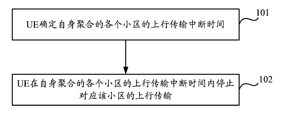
[0043] Such as figure 1 As shown, the flow chart of determining the uplink transmission interruption time for the UE, the method includes:

[0044] In step 101, the UE determines the uplink transmission interruption time of each cell aggregated by itself.

[0045] In the embodiment of the present invention, the UE determines the uplink transmission interruption time of each cell aggregated by itself, including but n...

Embodiment 2

[0127] In the embodiment of the present invention, the uplink transmission interruption time (union) caused by the measurement gap is determined based on the UE.

[0128] Suppose the UE aggregates two TDD Cells, denoted as Cell1 and Cell2 respectively, and Cell1 and Cell2 use TDD UL / DL configuration 2 and TDD UL / DL configuration 3 respectively; according to the UE capability reported by the UE, the UE works under the current frequency band combination Measuring the frequency point f requires measuring the gap, so when the base station configures the UE to perform frequency point f measurement, it needs to configure the measurement gap; however, since Cell1 and Cell2 use different TDD UL / DL configurations, the uplink transmission interruption time caused by the measurement gap The determination mechanism may determine the interruption time of uplink transmission on Cell1 and Cell2 respectively.

[0129] Such as image 3 The schematic diagram of determining the interruption tim...

Embodiment 3

[0133] In the embodiment of the present invention, the uplink transmission interruption time caused by the measurement gap is determined based on the UE (union, and the TDD Cell adopts dynamic UL / DL configuration).

[0134] Assuming that the UE aggregates two TDD Cells, which are respectively denoted as Cell1 and Cell2, and Cell1 adopts dynamic TDD configuration, in one radio frame, 1 / 4 of the subframe of Cell1 is a fixed DL subframe, and subframe 2 is a fixed UL subframe. Subframe 0 / 3 is a dynamic subframe; Cell2 adopts fixed TDD UL / DL configuration 3; according to the UE capability reported by the UE, the UE works under the current frequency band combination to measure the frequency point f and needs to measure the gap, so the base station configures the UE to perform frequency When measuring at point f, you need to configure the measurement gap; however, since Cell1 and Cell2 use different TDD UL / DL configurations, the uplink transmission interruption time on Cell1 and Cell2...


PUM


Abstract

The invention discloses a method for determining uplink transmission interruption time and equipment. The method comprises that UE (user equipment) determines the uplink transmission interruption time of every cell aggregated by the UE, and the UE stops the uplink transmission corresponding to the cell within the uplink transmission interruption time of every cell aggregated by the UE. According to embodiments, when the UE aggregates cells in different duplexing methods or cells with different TDD UL / DL configurations, through the determination of the uplink transmission interruption time of every cell aggregated by the UE, the uplink transmission interruption time caused by measuring the gap can be clearly determined, and thus the UE knows how to stop the uplink transmission corresponding to every cell.

Description

technical field [0001] The present invention relates to the field of communication technology, in particular to a method and device for determining the interruption time of uplink transmission. Background technique [0002] (1) TDD (Time Division Duplexing) UL (uplink) / DL (downlink) configuration; as shown in Table 1, the physical layer standard defines seven UL / DL configurations for TDD systems, where D stands for DL Subframe, U stands for UL subframe, and S stands for special subframe of TDD system. [0003] Table 1 TDD UL / DL configuration [0004] [0005] In general, the TDD UL / DL configuration of each cell is determined, which can be notified to the UE (User Equipment, user equipment) through a broadcast message; but in order to use resources more flexibly, LTE (Long Term Evolution, long-term evolution ) The system supports dynamic TDD UL / DL configuration, that is, some or all subframes in a wireless frame determine their transmission direction according to schedul...

Claims


Application Information

Patent Timeline
Patent Type & Authority Applications(China)
IPC IPC(8): H04W24/08H04W72/12
CPCH04W72/02H04W76/28H04L5/1469H04L43/0847H04W24/08H04W74/004
Inventor 赵亚利
Owner DATANG MOBILE COMM EQUIP CO LTD