Capping chuck assembly

A technology of chucks and components, applied in the direction of closures, pass-through elements, bottle/container caps, etc., capable of solving problems such as incorrect closing caps, application, etc.

Active Publication Date: 2013-12-25
CLOSURE SYST INT INC
View PDF5 Cites 4 Cited by
  • Summary
  • Abstract
  • Description
  • Claims
  • Application Information

AI Technical Summary

Problems solved by technology

Off-center contact between the bottom of the closure cap and the top of the associated container mouth can undesirably cause the closure cap to be incorrectly positioned in the capping chuck, resulting in application defects such as lifted or cross-snap closed lid

Method used


Image

  • Capping chuck assembly
  • Capping chuck assembly
  • Capping chuck assembly

Examples


Embodiment Construction

[0020] While the invention may be embodied in various forms, what is shown in the drawings and described below is a preferred embodiment of the invention, it being understood that the preferred embodiment of the invention is considered to be exemplary of the invention and is not intended to The invention is limited to the particular embodiment shown.

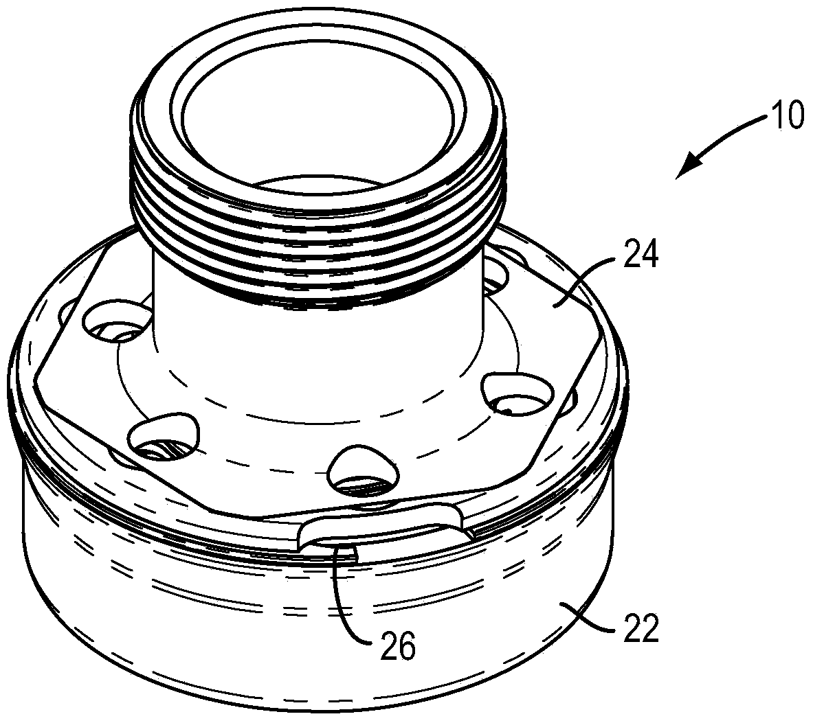
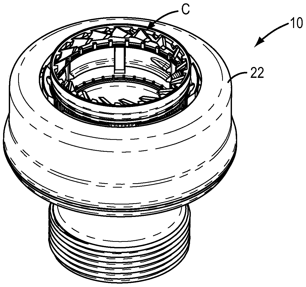
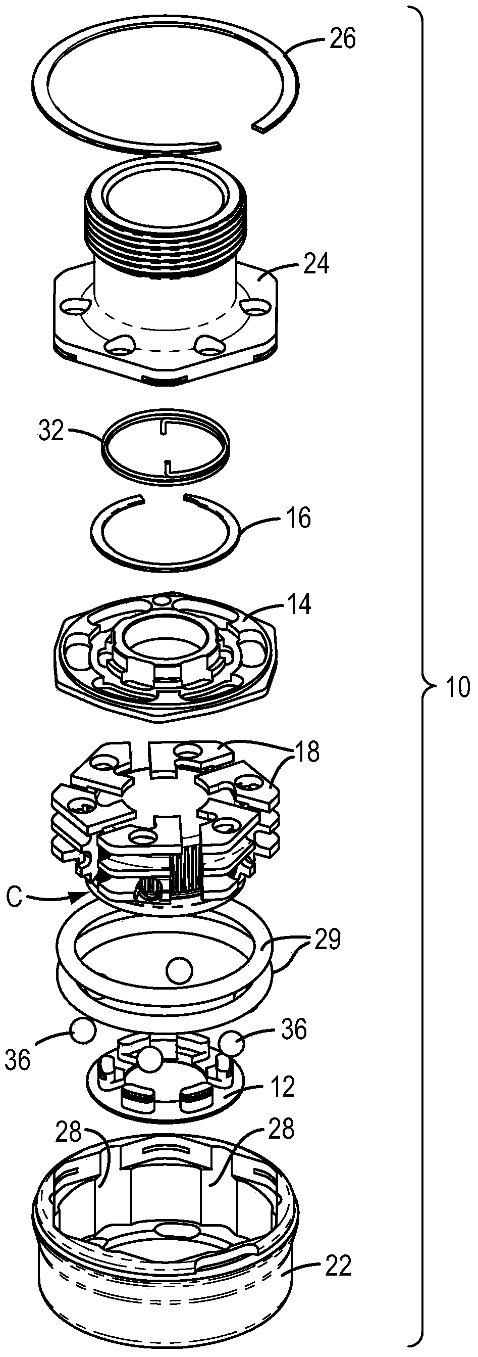
[0021] Referring now to the drawings, there is illustrated a capped chuck assembly 10 embodying the principles of the present invention. As will be appreciated by those skilled in the art, capping chuck assembly 10 is configured for use with high-speed automatic capping equipment for applying the threads of bottle caps to associated containers, such as on bottling machinery or the like. Filling operation. To this end, the capping chuck assembly is mounted into an associated rotary drive mechanism (not shown), whereby the capping chuck assembly is rotationally driven to rotationally apply the closure cap to the associated contai...


PUM


Abstract

A capping chuck assembly embodying the present invention comprises an outer chuck housing, and an inner central guide disc upon which a plurality of circumferentially spaced gripper segments are mounted. Each gripper segment includes an inner jaw portion for engagement with an associated closure, and an outer cam surface. The outer chuck housing defines a plurality of inwardly facing, cam drive surfaces positioned for respective engagement with the outer cam surfaces of the gripper segments, so that rotational drive of the outer chuck housing collectively drives the gripper segments and the guide disc to urge the segments radially into engagement with an associated closure.

Description

technical field [0001] The present invention relates generally to a capping head and chuck for rotatably applying a closure to an associated container, and more particularly to a capping head and chuck configured to automatically adapt to the closure during application of the closure to an associated container. Improved capping chuck assembly for cap variations, facilitating rapid application of closure caps while hopefully avoiding improper application of closure caps. Background technique [0002] Threaded plastic closures made of suitable polymeric materials have gained wide market acceptance for use on bottles and similar containers for carbonated and non-carbonated beverages. Efficient and versatile use of such closures is facilitated by the use of rapid, automatic capping equipment configured to rotatably apply each closure to an associated container to form the internal threads of said closure Threadingly engages and mates with external thread forming provided on the...

Claims


Application Information

Patent Timeline
Patent Type & Authority Applications(China)
IPC IPC(8): B67B1/06
CPCB67B3/2066Y10T279/17025Y10T279/17717B67B1/06
Inventor K·E·策姆林
Owner CLOSURE SYST INT INC
Why Eureka
Try Eureka