
Instant start ballast system

A technology of ballasts and receivers, applied in the field of program start ballasts, which can solve problems such as shortening lamp life

Inactive Publication Date: 2013-12-25
KONINKLJIJKE PHILIPS NV
View PDF2 Cites 0 Cited by
  • Summary
  • Abstract
  • Description
  • Claims
  • Application Information

AI Technical Summary

Problems solved by technology

[0010] In lighting systems where electronic ballasts are frequently switched on and off, the light should be switched on immediately or after a very short time delay, and this should not shorten the life of the lamp

Method used


Image

  • Instant start ballast system
  • Instant start ballast system
  • Instant start ballast system

Examples


Embodiment Construction

[0027] What follows is the best contemplated mode of carrying out the invention. This description is given for the purpose of illustrating the general principles of the invention and should not be construed as limiting. The scope of the invention is best determined with reference to the appended claims.

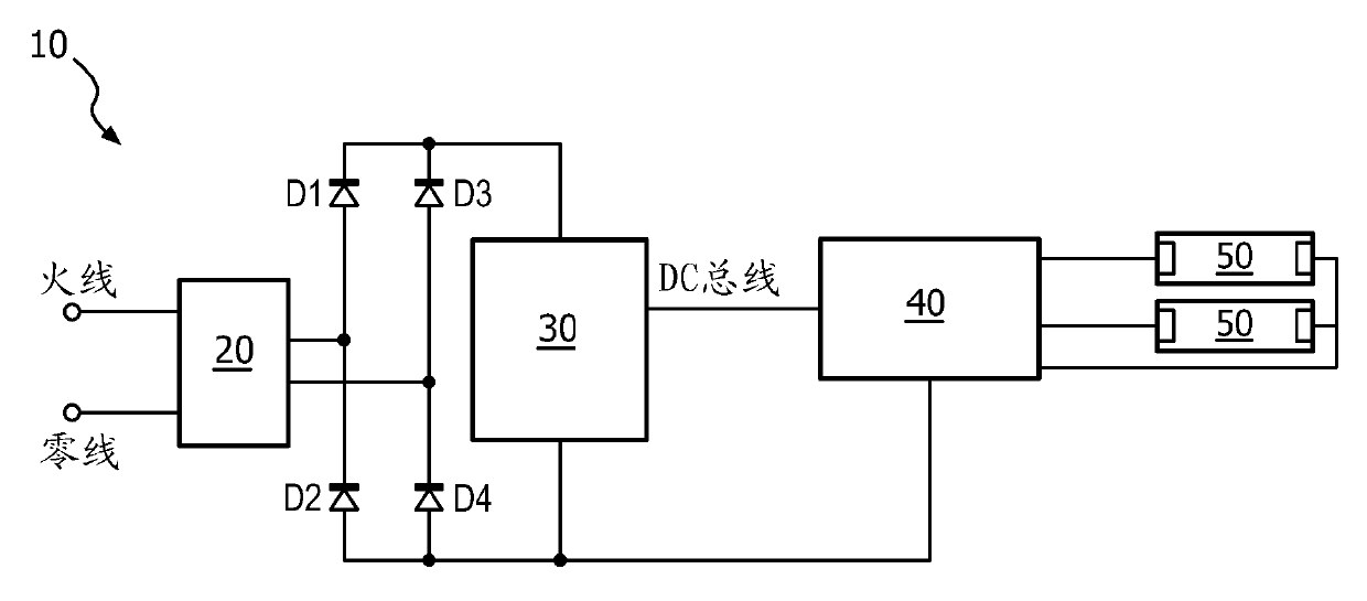
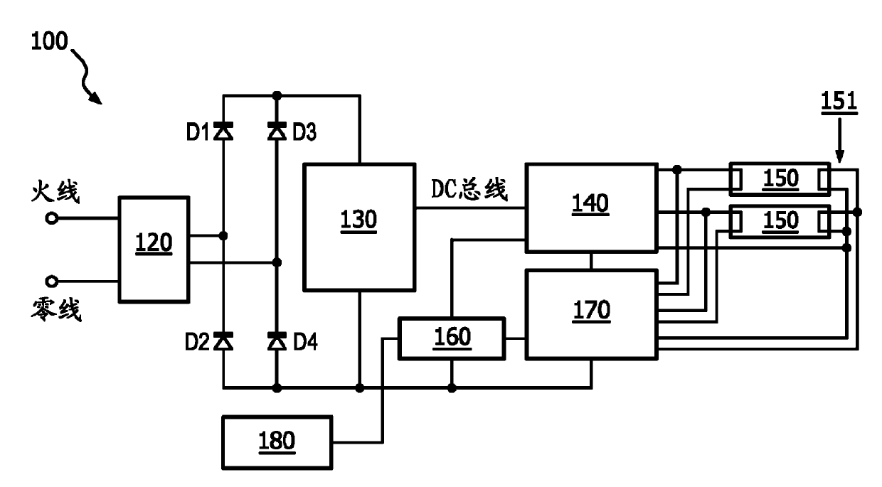
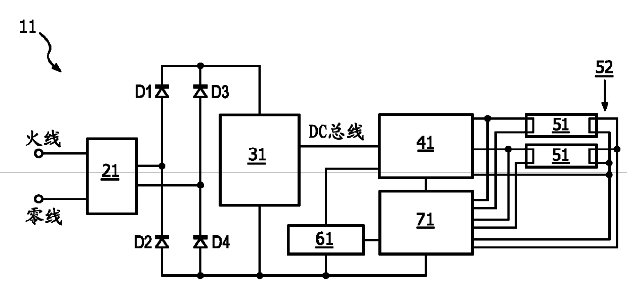
[0028] image 3 is a block diagram of a ballast system 100 according to a first embodiment of the present invention. The system 100 includes an EMI filter 120 , bridge diodes ( D1 - D4 ), a PFC converter 130 , an inverter 140 , a heating circuit 160 , a controller heating circuit 170 , and one or more lamps 150 . The lamps 150 may be connected in series or in parallel. Such as image 3 As shown, lamps 150 are connected in parallel. Common connections of one or more filaments 151 of lamp 150 (ie, the right side of lamp 150 ) may be in series or in parallel. Such as image 3 As shown, the filaments 151 are connected in parallel.

[0029] and figure 2 In contrast to th...


PUM


Abstract

A program-start ballast(100) that is connectable to a lamp (150) with a filament (151) is disclosed. The ballast includes a heating unit (170) arranged to heat the filament (151), a receiver (180) arranged to receive a signal to turn the lamp (150) on or off, and a control circuit (160) arranged to turn the lamp (150) on or off based upon an output of the receiver (180). The heating unit (160) is further arranged to heat the filament (151) before the signal to turn the lamp on is received by the receiver (180) and keep the filament (151) heated after the signal to turn off the lamp is received by the receiver (180).

Description

technical field [0001] The present invention relates to electronic ballasts, and more particularly to a program start ballast that includes an occupancy signal receiver and a heat controller that provides constant heat to the filament to allow rapid start. Background technique [0002] Electronic lamp ballasts use solid-state electronic circuitry to provide the proper starting and operating electrical conditions to power one or more fluorescent and / or high-intensity discharge (HID) lamps. In addition, high-efficiency, high-frequency electronic ballasts are known to give superior lighting performance and energy savings, which makes their use cost-effective. Electronic ballasts are available for fixed lights, as well as full-range dimming models. [0003] The first major category of electronic ballasts are instant start ballasts. Conventional instant-start ballasts start the lamp without heating the cathode of the lamp by applying high voltage (around 600 volts). Such conve...

Claims


Application Information

Patent Timeline
Patent Type & Authority Applications(China)
IPC IPC(8): H05B41/295H05B41/38
CPCH05B41/295H05B47/19H05B41/36
Inventor Y.方A.加内斯
Owner KONINKLJIJKE PHILIPS NV
Learn More