A control system of presser foot lifter electromagnet driven by multi-mode output

A technology of output drive and control system, which is applied in control devices for sewing machines, cloth press mechanisms, textiles and papermaking, etc. It can solve problems such as the mechanical structure of the presser foot that is easily damaged, the service life of the presser foot is short, and the quality of the product is affected. Achieve the effects of avoiding fabric damage, prolonging service life and avoiding equipment loss

Active Publication Date: 2020-02-28
ZHEJIANG UNIV
View PDF6 Cites 0 Cited by
  • Summary
  • Abstract
  • Description
  • Claims
  • Application Information

AI Technical Summary

Problems solved by technology

[0003] In the existing presser foot lifting electromagnet drive circuit, a constant voltage power supply is usually used. The electromagnet is driven by high voltage in the working state and conducts a large current for a long time. current, it will cause the electromagnet to overheat, easily damage itself, and even cause personal danger
[0004] In the existing presser foot lifting electromagnet drive circuit, when the presser foot is switched from lifting to lowering, the electromagnet directly releases the connecting piece connected to the presser foot assembly, and the presser foot in the presser foot assembly moves down quickly under the action of the transmission structure , and produce mechanical impact with the contact surface, it is easy to damage the mechanical structure of the presser foot, resulting in the problem of short service life of the presser foot
At the same time, during the working process of the sewing machine, the mechanical impact between the presser foot and the fabric will leave traces on the fabric, affecting product quality

Method used


Image

  • A control system of presser foot lifter electromagnet driven by multi-mode output

Examples


Embodiment Construction

[0031] The present invention will be described in further detail below in conjunction with the accompanying drawings and specific embodiments, but the implementation method of the present invention is not limited thereto.

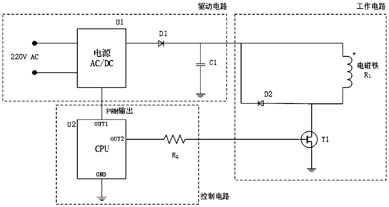
[0032] Such as figure 1 As shown, the present embodiment provides a multi-mode output-driven presser foot lifter electromagnet control system, including: a driving circuit, a control circuit and a working circuit.

[0033] The driving circuit includes a power supply unit U1, a diode D1 and a capacitor C1; the power supply unit U1 includes two AC input terminals, a control terminal and an output terminal, and the two AC input terminals of the power supply unit U1 are electrically connected to a 220V AC power supply, and the output of the power supply unit U1 terminal is electrically connected to the anode of the diode D1, the cathode of the diode D1 is electrically connected to the first end of the capacitor C1, and the second end of the capacitor C1 is grou...


PUM


Abstract

The invention discloses a multi-mode output driven type presser foot lifting electromagnet control system. The system comprises a driving circuit, a control circuit and a work circuit, wherein the driving circuit comprises a power unit, a first diode and a capacitor unit; the control circuit comprises a micro processor and a resistor unit; the work circuit comprises a switch unit, an electromagnetand a second diode; the micro processor controls the power unit to output linear adjustable direct-current voltage, and the voltage can be adjusted to 0 V; the micro processor controls the switch unit to be switched on or off. By means of the multi-mode output driven type presser foot lifting electromagnet control system, the problem is solved that when continuously working, the electromagnet istoo hot and damaged, and the problems are solved that in the process that the lifting state of a presser foot is changed into a lowering state of the presser foot, the mechanical shock between the presser foot and the contact surface is large, so that the device is short in service life and a fabric is damaged, and it is achieved that the electromagnet is quickly started.

Description

technical field [0001] The invention relates to the field of electronic circuits, in particular to a multi-mode output driven presser foot lifting electromagnet control system. Background technique [0002] At present, many industrial sewing machines adopt an automatic presser foot lifting mechanism to reduce the labor intensity of operators and improve labor efficiency. Existing automatic presser foot lifting mechanism is generally driven by electromagnet. [0003] In the existing presser foot lifting electromagnet drive circuit, a constant voltage power supply is usually used. The electromagnet is driven by high voltage in the working state and conducts a large current for a long time. If the current is too high, it will cause the electromagnet to overheat, easily damage itself, and even cause personal danger. [0004] In the existing presser foot lifting electromagnet drive circuit, when the presser foot is switched from lifting to lowering, the electromagnet directly r...

Claims


Application Information

Patent Timeline
Patent Type & Authority Patents(China)
IPC IPC(8): D05B29/02D05B69/10
CPCD05B29/02D05B69/10D05D2207/05
Inventor 黄文君张阳阳许伟杰周逊盛
Owner ZHEJIANG UNIV
Why Eureka
Try Eureka