The Ejector Mechanism of the Die-casting Mold Without the Imprint of the Ejector Rod

A technology of ejector mechanism and no ejector rod, which is applied in the field of die-casting molds, can solve the problems of high operation requirements, high production cost, and long production cycle, and achieve the effect of simple operation, low production cost, and short production cycle

Active Publication Date: 2016-03-09
NINGBO HELI TECH CO LTD
View PDF7 Cites 0 Cited by
  • Summary
  • Abstract
  • Description
  • Claims
  • Application Information

AI Technical Summary

Problems solved by technology

The ejection mechanism of the die-casting mold in the prior art all uses the movable push plate to eject the casting, but the slag bag, the runner and the casting are pushed out at the same time when the movable push plate is ejected, so that the slag bag, the runner and the casting are still embedded in the In the push plate, the worker needs to operate manually to disengage from the push plate, but this operation requires high operation, otherwise the casting is prone to slag pockets or grooves on the casting after the sprue breaks during disengagement , which leads to the scrapping of castings; or it is easy to produce marks on castings, which leads to scrapping of castings
Therefore, the ejection mechanism of the die-casting mold in the prior art without the ejector pin mark has the problems of low ejection efficiency, low yield rate, long production cycle and high production cost.

Method used


Image

  • The Ejector Mechanism of the Die-casting Mold Without the Imprint of the Ejector Rod
  • The Ejector Mechanism of the Die-casting Mold Without the Imprint of the Ejector Rod

Examples


Embodiment Construction

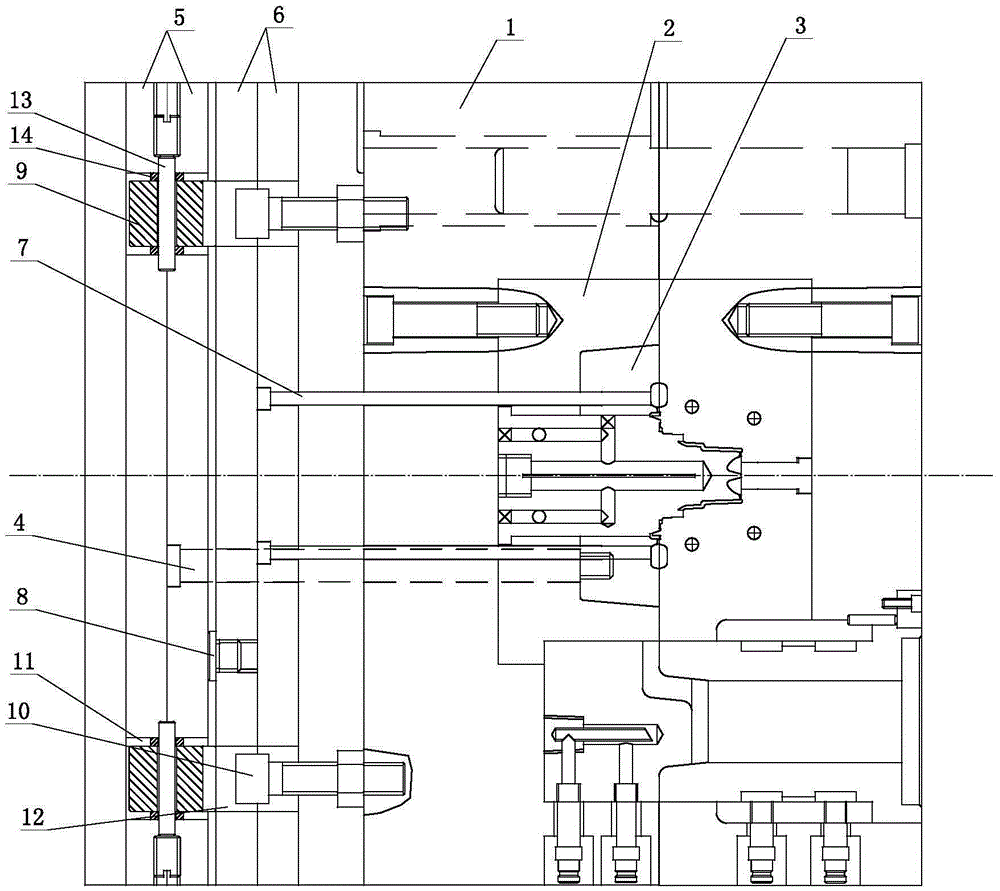
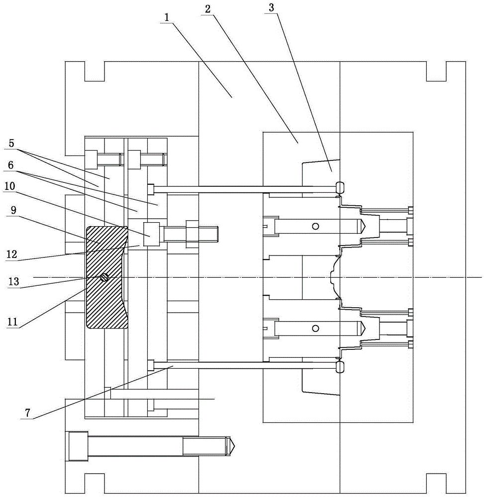
[0014] The present invention will be further described below with reference to the accompanying drawings and specific embodiments.

[0015] like figure 1 and figure 2 The shown ejection mechanism without ejector pin marks of a die-casting mold includes a movable mold 1, a movable mold meat 2 embedded in the movable mold 1, a push plate 3 located in the movable mold meat 2, and a push plate ejector column 4. And the top plate 5 that is slidingly connected with the movable die 1 (of course it also includes other parts, but since it does not involve the invention of the present invention, it will not be repeated here), one end of the push plate top column 4 is connected to the push plate 3 Connection, the other end of the push plate top column 4 is over-moving die 1 and the movable die meat 2 are fixedly connected to the top plate 5, and a secondary top plate 6 for ejecting the slag bag is provided between the top plate 5 and the movable die 1. The secondary top plate 6 is pro...


PUM


Abstract

An ejection mechanism for die-casting moulds without marks of ejector rods comprises a movable mould (1), a movable mould base (2), a pushing plate (3), a pushing plate ejecting column (4) and an ejecting plate (5), wherein the movable mould base (2) is inlaid in the movable mould (1); the pushing plate (3) is positioned in the movable mould base (2); the ejecting plate (5) is slidably connected with the movable mould (1); one end of the pushing plate ejecting column (4) is connected with the pushing plate (3); the other end of the pushing plate ejecting column (4) is fixedly connected with the ejecting plate (5) through the movable mould (1) and the movable mould base (2); a secondary ejecting plate (6) for ejecting cinder ladles outwards is arranged between the ejecting plate (5) and the movable mould (1); an ejector pin (7) is arranged on the secondary ejecting plate (6); one end of the ejector pin (7) is fixed on the secondary ejecting plate (6); and the end surface of the other end of the ejector pin (7) is flush with a mould cavity wall corresponding to a cinder ladle on the pushing plate (3) through the movable mould (1), the movable mould base (2) and the pushing plate (3). Compared with the prior art, the ejection mechanism has the advantages of high ejection efficiency, high yield, short production period and low production cost.

Description

technical field [0001] The invention belongs to the field of die-casting molds, and particularly relates to an ejector mechanism without ejector pin marks in the die-casting mold. Background technique [0002] At present, among all kinds of die castings, there is a type with a large area and a relatively regular shape. The surface of these castings is not allowed to have ejection marks, and the castings are required to meet the assembly requirements without processing. The ejection mechanism of the die-casting die in the prior art all use the moving push plate to push out the casting, but the slag ladle, the runner and the casting are pushed out at the same time when the movable push plate is pushed out, so the slag ladle, the runner and the casting are still embedded. In the push plate, it needs another manual operation by the worker to be disengaged from the push plate, but this operation requires higher operation, otherwise the slag ladle or the grooves generated on the c...

Claims


Application Information

Patent Timeline
Patent Type & Authority Patents(China)
IPC IPC(8): B22D17/22
Inventor 姬斌斌史荣荣
Owner NINGBO HELI TECH CO LTD
Why Eureka
Try Eureka