Modular bullet holder device

A modular and pop-up technology, applied in wellbore/well components, production fluid, earthwork drilling and production, etc., can solve problems such as inability to perform angle-changing operations, unfavorable adjustment of perforating charges, unsatisfactory fixing methods, etc., to achieve fixed convenient effect

Active Publication Date: 2014-01-01
BC P INC CHINA NAT PETROLEUM CORP +1
View PDF5 Cites 2 Cited by
  • Summary
  • Abstract
  • Description
  • Claims
  • Application Information

AI Technical Summary

Problems solved by technology

[0006] 1. The fixing method of the existing bullet support device is not ideal, and the bullet support that completely surrounds the perforating charge is not conducive to adjusting the firing direction of the perforating charge to align with the dip angle fractured reservoir of oil and gas wells on high and steep structural belts
[0007]...

Method used


Image

  • Modular bullet holder device
  • Modular bullet holder device
  • Modular bullet holder device

Examples


Embodiment 1

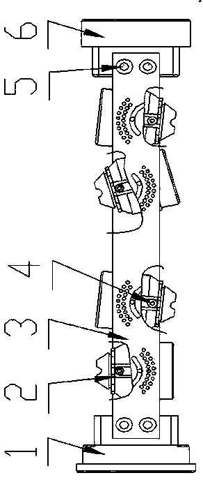
[0042] As a preferred embodiment of the present invention, the present invention discloses a modular bullet support device, comprising an upper bullet support plate 13, a lower bullet support plate 9 and two bullet support plates 10, an upper bullet support plate 13 and a lower bullet support plate The supporting plate 9 is provided with a bullet hole 17 for matching the outer diameter of the perforating charge 7. The upper bullet supporting plate 13 and the lower bullet supporting plate 9 are connected and fixed by means of the bullet supporting plate 10, and the bullet supporting plate 10 is connected to There are hinge shaft 4 and chute pin 11, and at least one indexing fixing hole 12 is also processed on the bullet support plate 10. 12 is located on the support plate 10 close to the upper support plate 13, and the chute pin 11 is located between the hinge shaft 4 and the indexing fixing hole 12;

[0043] The modular bullet rest device is applied to a variable firing angle ...

Embodiment 2

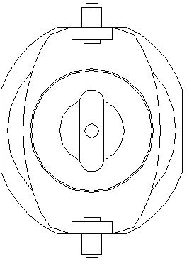
[0046] As another preferred embodiment of the present invention, on the basis of Example 1, the hinge shaft hole 36, the adjustment chute 35 and the arc-shaped indexing hole 37 on the orientation square structure 33 are distributed in groups, and two adjacent groups The perforation direction of the perforating charge 7 in the modular bullet rest device 2 is opposite and adjustable. There are two rows of indexing holes 37 arranged on the orientation square structure 33 . The orientation square structure 33 is plate-shaped.

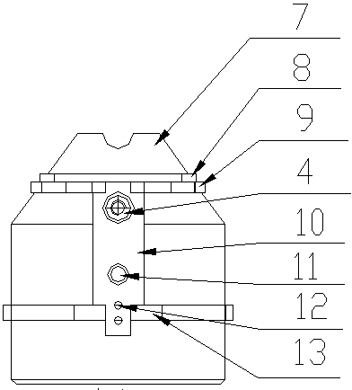
[0047] Fixed ring 1 comprises circular head 38, is provided with two fixed plates 39 arranged in parallel on circular head 38, two fixed plates 39 and head 38 vertical and integrated molding, on two fixed plates 39 Pin holes 40 are processed, and the two fixing plates 39 are respectively fixed on the two directional square structures 33 via the fixing pins 5 , and steps are arranged on the circular head 38 .

[0048] Backing ring 6 comprises circular head...

Embodiment 3

[0050]As yet another preferred embodiment of the present invention, on the basis of Example 2, there are two indexing and fixing holes 12 on the bullet support plate 10 . The upper part of the perforating charge 7 is cylindrical, and the lower part is in the shape of an inverted truncated cone. A step 31 and a limiting groove 32 are provided on the lower part of the perforating charge 7 in the shape of a truncated cone. The lower bullet support plate 9 is embedded in the limiting groove 32 .


PUM


Abstract

The invention discloses a modular bullet holder device, and relates to the technical field of oil-gas well perforation completion. The modular bullet holder device comprises an upper bullet holder plate, a lower bullet holder plate and two bullet holder support plates. Bullet holes matching with perforating bullets in external diameter are formed in the upper bullet holder plate and the lower bullet holder plate, the upper bullet holder plate and the lower bullet holder plate are mutually connected and fixed by the aid of the bullet holder support plates, a hinge shaft and a chute pin are connected onto each bullet holder support plate, and at least one dividing and fixing hole is processed in each bullet holder support plate. Each hinge shaft is located at the position, close to the lower bullet support plate, of the corresponding bullet holder support plate, and each chute pin is positioned between each hinge shaft and the corresponding dividing and fixing hole. The modular bullet holder device has the advantages that an original fixing mode of the perforating bullets is changed to the benefit of adjusting a perforating bullet shooting direction to align to an oblique fractured reservoir of an oil-gas well on a high-steep structural belt, and independent modular locking and supporting of the perforating bullets are realized.

Description

[0001] technical field [0002] The invention relates to the technical field of oil and gas well perforation and completion operations, and in particular relates to a modular flick support device. Background technique [0003] At present, in the conventional oil and gas reservoirs explored and developed by major oil and gas fields in the world, some oil and gas wells have extremely developed natural fractures in a certain direction of the high-steep structural belt. The channels are seldom aligned with natural fractures, so that the single-well productivity of oil and gas wells is not high, and sand production wells will also be accompanied by severe sand production, which will also bring greater wellhead construction pressure to subsequent production stimulation measures, and the production stimulation effect cannot be achieved. [0004] The publication number is CN202381054U, and the Chinese patent document with the publication date of August 15, 2012 discloses an ener...

Claims


Application Information

Patent Timeline
IPC IPC(8): E21B43/119
Inventor 陈华彬唐凯陈锋郭晓燕陈建波王海李妍僖
Owner BC P INC CHINA NAT PETROLEUM CORP
Why Eureka
Try Eureka