Centrifugal fan

A centrifugal fan and fan blade technology, which is applied to the components of the pumping device for elastic fluids, non-variable pumps, machines/engines, etc., can solve problems such as noise and centrifugal fan pressure loss, and avoid Pressure loss, noise reduction, noise reduction effect

Inactive Publication Date: 2014-01-01
FURUI PRECISE COMPONENT (KUNSHAN) CO LTD +1
View PDF4 Cites 4 Cited by
  • Summary
  • Abstract
  • Description
  • Claims
  • Application Information

AI Technical Summary

Problems solved by technology

When the centrifugal fan is working, the high-pressure airflow generated by the impeller accumulates between the impeller and the side plate, part of the high-pressure airflow rebounds from the sidewall and flows into the impeller, and mixes with the natural airflow entering the impeller, which not only causes the pressure loss of the centrifugal fan , also cause noise

Method used


Image

  • Centrifugal fan
  • Centrifugal fan
  • Centrifugal fan

Examples


Embodiment Construction

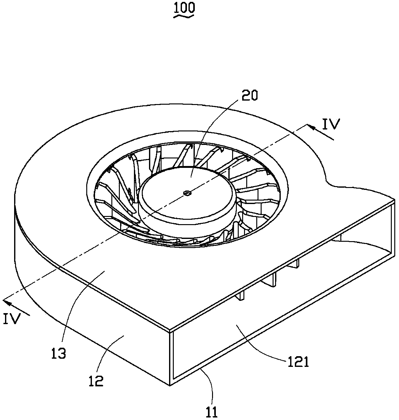
[0015] see Figure 1 to Figure 4 , is a centrifugal fan 100 according to the first embodiment of the present invention, and the centrifugal fan 100 includes a fan frame 10 and an impeller 20 accommodated in the fan frame 10 .

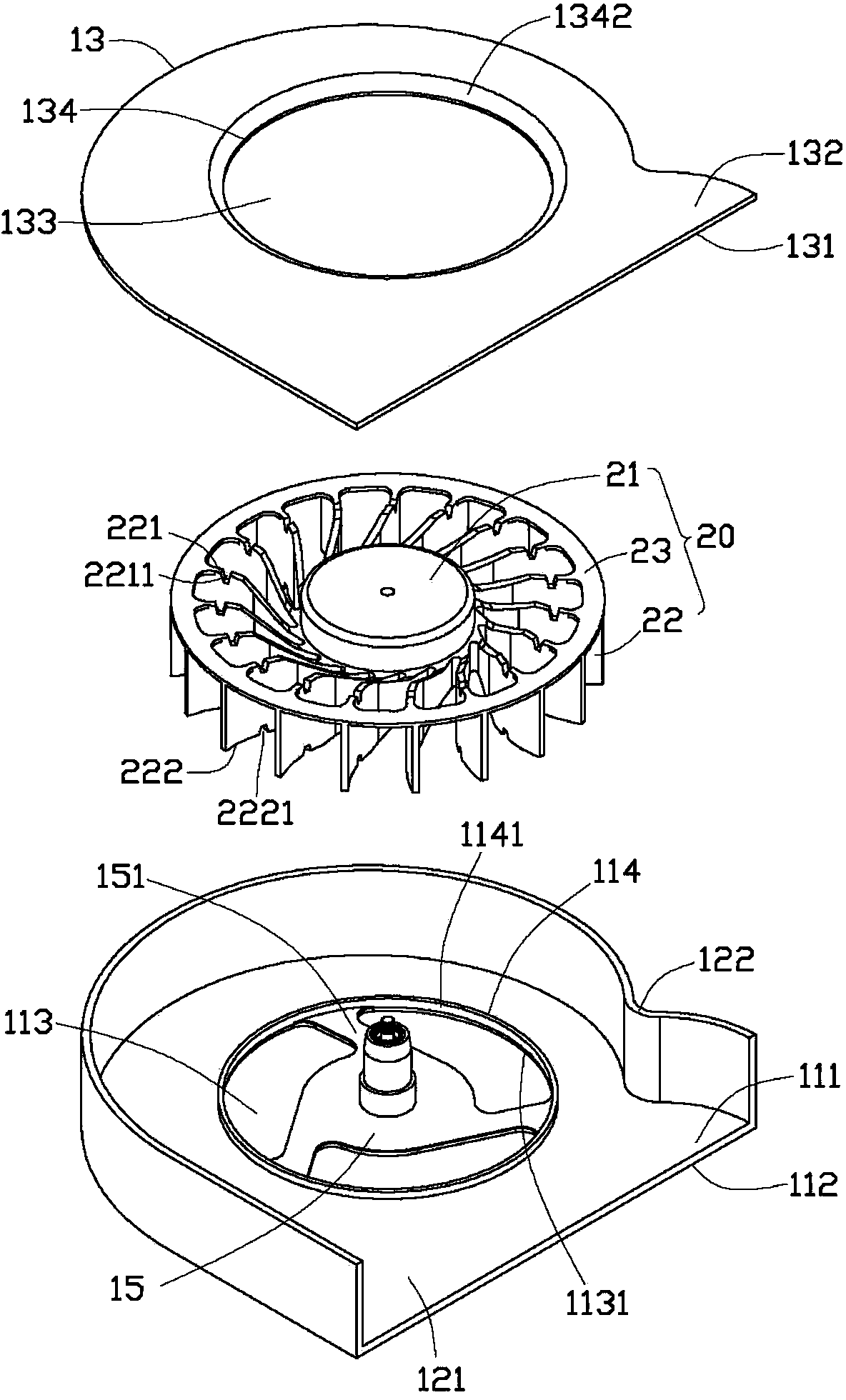
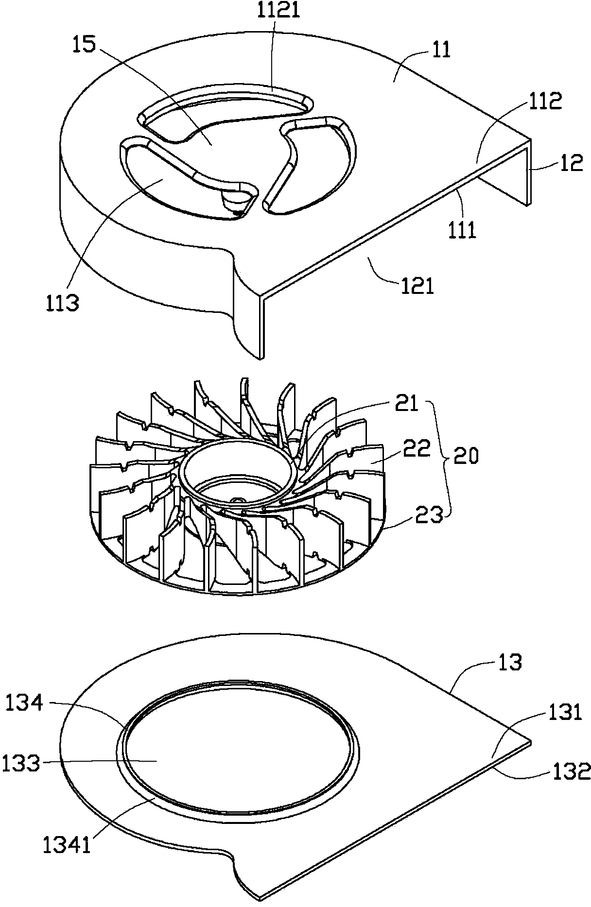
[0016] The fan frame 10 includes a bottom plate 11 , a side plate 12 extending upward from a periphery of the bottom plate 11 , and a cover plate 13 covering a top end of the side plate 12 . The base plate 11 , the side plate 12 and the cover plate 13 together form a receiving space 14 for receiving the impeller 20 .

[0017] The bottom plate 11 includes an inner surface 111 facing the impeller 20 and an outer surface 112 opposite to the inner surface 111 and facing away from the impeller 20 . The side plate 12 is located on a side where the inner surface 111 is located. A fixing seat 15 is disposed in the middle of the bottom plate 11 , and three first air inlets 113 are formed on the outer periphery of the fixing seat 15 in the middle of the bottom ...


PUM


Abstract

The invention provides a centrifugal fan, which comprises a fan frame and an impeller accommodated in the fan frame, wherein the fan frame comprises a bottom plate, a cover plate and side plates, the side plates are positioned between the bottom plate and the cover plate, the bottom plate comprises an inner surface facing the impeller and an outer surface opposite to the inner surface, the middle part of the bottom plate is provided with a fixing seat, the impeller is rotationally and fixedly arranged on the fixing seat, the bottom plate is provided with a plurality of first air inlet openings penetrating through the inner surface and the outer surface on the outer periphery of the fixing seat, a first connecting arm is formed between the two adjacent first air inlet openings, and is connected between the fixing seat and the bottom plate, each first air inlet is provided with an arc-shaped outer side edge opposite to the fixing seat, the inner surface of the bottom plate is provided with first convex rings projecting and extending towards the impeller on the outer periphery of the first air inlet openings, the arc-shaped outer side edges of the first air inlet openings are coincident with the inner walls of the first convex rings, chamfered surfaces are formed on the outer surface at the edge of each first air inlet opening, and the chambered surfaces are inclined to face one side of the outer surface and have arc-shaped cross sections.

Description

technical field [0001] The invention relates to a fan, in particular to a centrifugal fan for cooling electronic components. Background technique [0002] With the rapid development of the computer industry, the heat dissipation problem derived from the pursuit of high speed, high function and miniaturization of CPU is becoming more and more serious, which is more prominent in electronic devices with small internal space such as notebook computers. If the heat generated by electronic components such as the CPU cannot be dissipated in a timely and effective manner, the performance of the electronic components will be greatly affected, and the service life of the electronic components will also be shortened. Therefore, it is necessary to dissipate heat from the electronic components. [0003] At present, the industry often uses centrifugal fans to dissipate heat from electronic components. An impeller in the accommodation space, the bottom plate and the cover plate are provid...

Claims


Application Information

Patent Timeline
Patent Type & Authority Applications(China)
IPC IPC(8): F04D29/42F04D29/28F04D29/66
Inventor 刘智仁徐伟杭
Owner FURUI PRECISE COMPONENT (KUNSHAN) CO LTD
Why Eureka
Try Eureka