[0008]It is therefore an object of the invention to provide a self-propelled vacuum cleaning device that functions in an automatic manner, and cleans textile floor coverings better, while having a compact structure.
[0012]In order to be able to use the vacuum cleaning device well in the
private home sector, a low device height and, at the same time, a small base area are aimed at. Preferably, the vacuum cleaning device has a base area between 1000 cm2 and 1500 cm2. Within the framework of the invention, the base area is the area that is covered by the vacuum cleaning device in the case of a
vertical projection. If the base area is small, particularly if the base area lies in the range indicated, it is possible for the vacuum cleaning device to reach nooks as well, making it possible to achieve complete cleaning even in regions where access is difficult. For the purpose of good maneuverability, it is practical if the base area is configured to be round or oval.
[0014]In order to achieve a further improvement in the suction behavior within the framework of an advantageous embodiment of the invention, seals are provided between the individual components, along the path of the air
stream, in the vacuum cleaning device. The proportion of useless air that is drawn in not through the suction mouth but rather through cracks and openings between the components can be minimized by such seals. The flow cross-sections and flow transitions along the path of the suction air can also be optimized, in terms of flow technology, in order to avoid pressure losses.
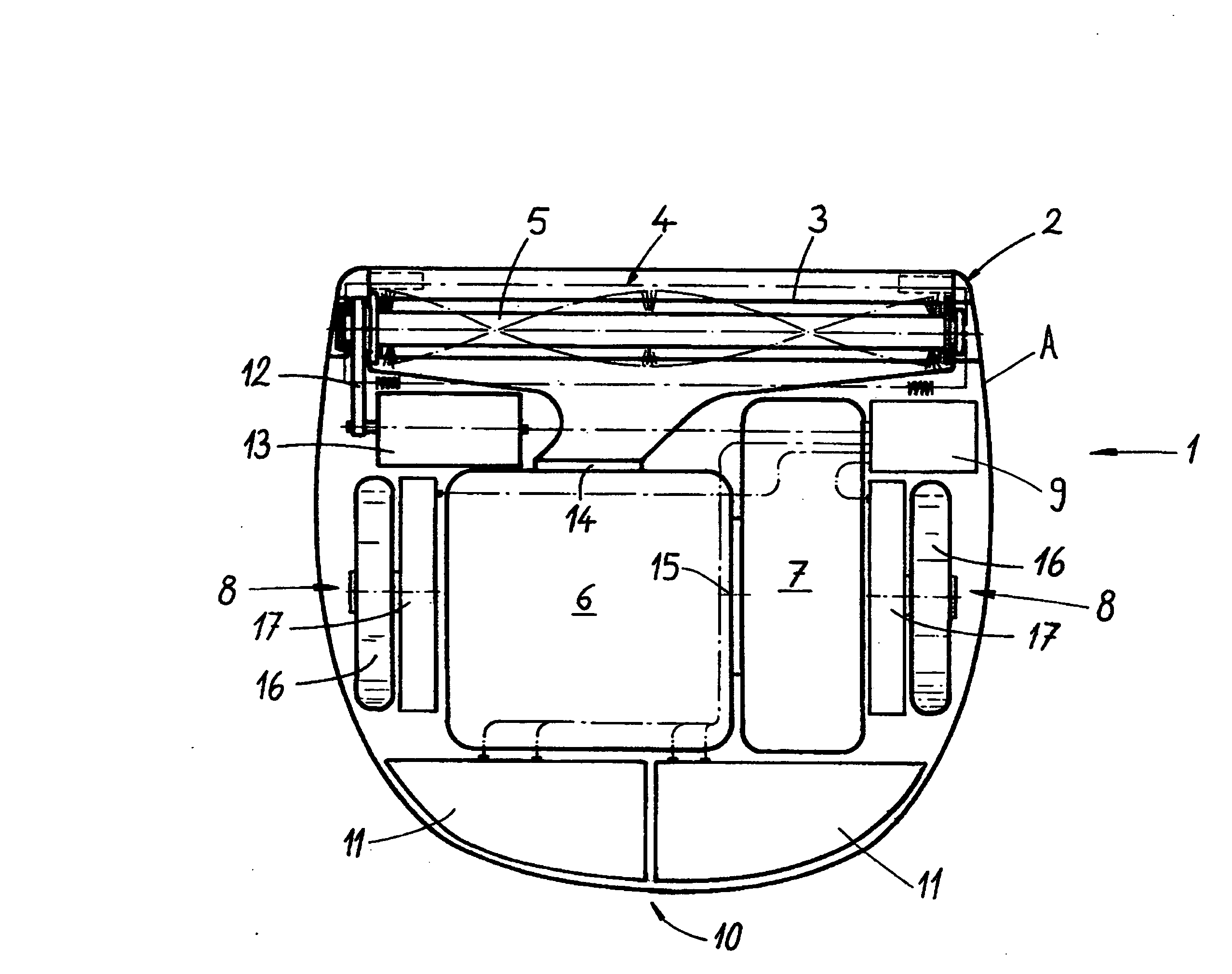
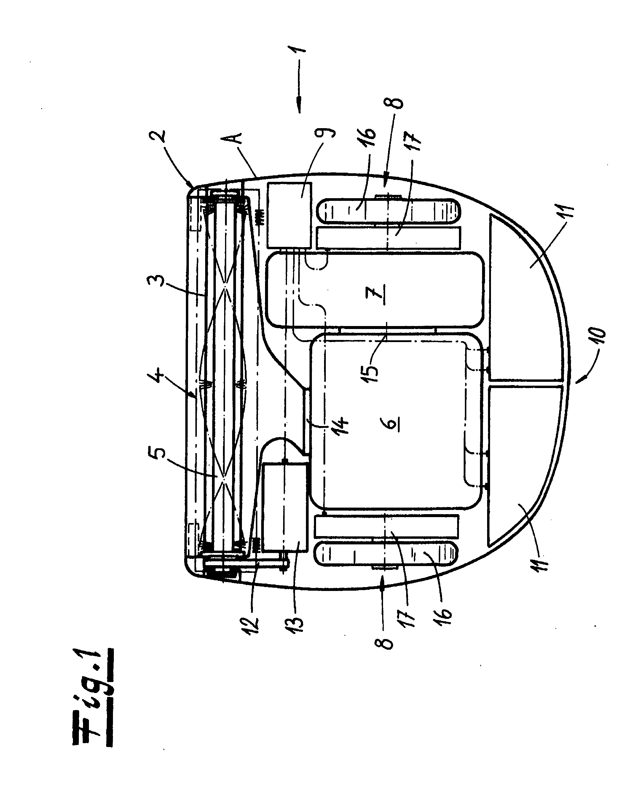
[0015]The cleaning roller provided according to the invention is disposed in an assigned roller chamber, and the suction mouth can be disposed on the underside of the housing, at a distance from the roller. However, in a preferred embodiment of the invention, the suction mouth is disposed on the underside of the roller chamber, and the suction air is guided from the roller chamber to the dust collection container. The cleaning roller can be driven electrically or by an air
turbine, and contributes to cleaning by direct contact of the roller surface with the
floor covering. In order to guarantee contact between cleaning roller and
floor covering on different floor coverings, and to avoid increased friction between
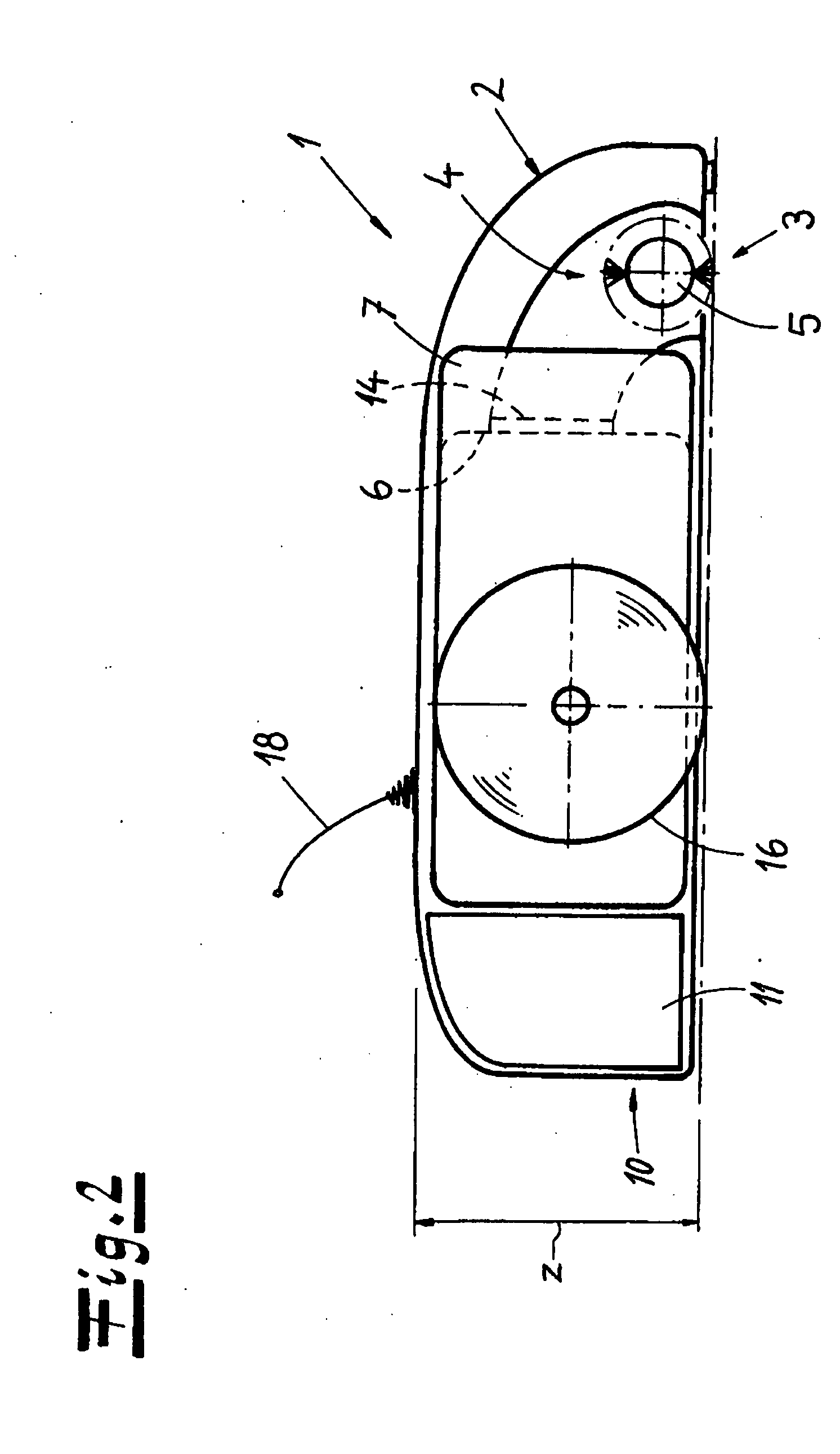
floor covering and cleaning roller, the cleaning roller is preferably mounted in the housing so that it is resilient in the vertical direction. Alternatively, the roller chamber, with suction mouth and cleaning roller, can be mounted in the housing, as a whole, to be resilient in the vertical direction. The roller chamber can rest on the floor, in sections, with its underside or with rollers and / or slide surfaces. Both in the case of a resiliently mounted cleaning roller and in the case of a resiliently mounted roller chamber, the optimal
contact pressure of the cleaning pressure, and a distance between the suction mouth and the surface to be cleaned that is advantageous from a flow-technology point of view can be achieved by a corresponding
spring force of the resilient mounting. For example, the cleaning roller can be configured as a lamella roller having soft, resilient lamellae made of plastic, or as a
brush roller. Preferably, soft bristles are provided, which lead to
low friction between cleaning roller and floor covering.
[0016]The vacuum cleaning device according to the invention cleans different floor coverings well, and is suitable for picking up large amounts of
dirt in a short time, also because of the large air
stream. In order to match the improved suction properties, the volume of the dust collection container is greater than 1
liter. Such a configuration can be implemented even in combination with the compact construction described above, by means of effective utilization of the
available volume.

