Cordierite-based ceramic honeycomb filter and its production method

a technology of cordierite and ceramics, applied in the direction of combination devices, machines/engines, domestic applications, etc., can solve the problems of large pressure loss, short capture time, and high production cost, and achieve the effect of improving strength and low pressure loss

Active Publication Date: 2013-08-06
HITACHI METALS LTD
View PDF36 Cites 19 Cited by
  • Summary
  • Abstract
  • Description
  • Claims
  • Application Information

AI Technical Summary

Benefits of technology

[0013]Accordingly, an object of the present invention is to provide a ceramic honeycomb filter having low pressure loss and improved strength to withstand mechanical vibration and shock, even when used as industrial ceramic honeycomb filters for construction machines, etc. or large ceramic honeycomb filters of more than 200 mm in outer diameter.DISCLOSURE OF THE INVENTION
[0014]As a result of intensive research in view of the above object, the inventors have found that a well-balanced combination of pores effective for low pressure loss and pores effective for high strength can prevent the pressure loss from deteriorating with relatively low porosity. The present invention has been completed based on such finding.

Problems solved by technology

Exhaust gases from diesel engines contain particulate matter (PM) based on carbonaceous soot and SOFs (soluble organic fractions) of high-boiling-point hydrocarbons, and the release of PM into the atmosphere is likely to exert adverse effects on humans and environment.
Particularly the capturing efficiency and the pressure loss are in a reciprocal relation; higher capturing efficiency results in larger pressure loss and shorter capturing time, and lower pressure loss results in longer capturing time and poorer capturing efficiency.
However, particularly when used for industrial ceramic filters for construction machines, etc. or large ceramic honeycomb filters of more than 200 mm in outer diameter, the honeycomb filters of Examples 1, 2 and 5 have too large average pore sizes or porosities, resulting in insufficient strength, and the honeycomb filter of Example 6 has too small porosity, resulting in high pressure loss.
However, the porous honeycomb filter described in JP 2002-219319 A does not have sufficiently low pressure loss particularly when used as industrial filters for construction machines, etc., or large filters of more than 200 mm in outer diameter.
However, the use of quartz and silica particles shown in Table 2 of JP 2004-250324 A provides ceramic honeycomb filters with too high percentage of fine pores, resulting in high pressure loss.

Method used


Image

  • Cordierite-based ceramic honeycomb filter and its production method
  • Cordierite-based ceramic honeycomb filter and its production method
  • Cordierite-based ceramic honeycomb filter and its production method

Examples


example 1

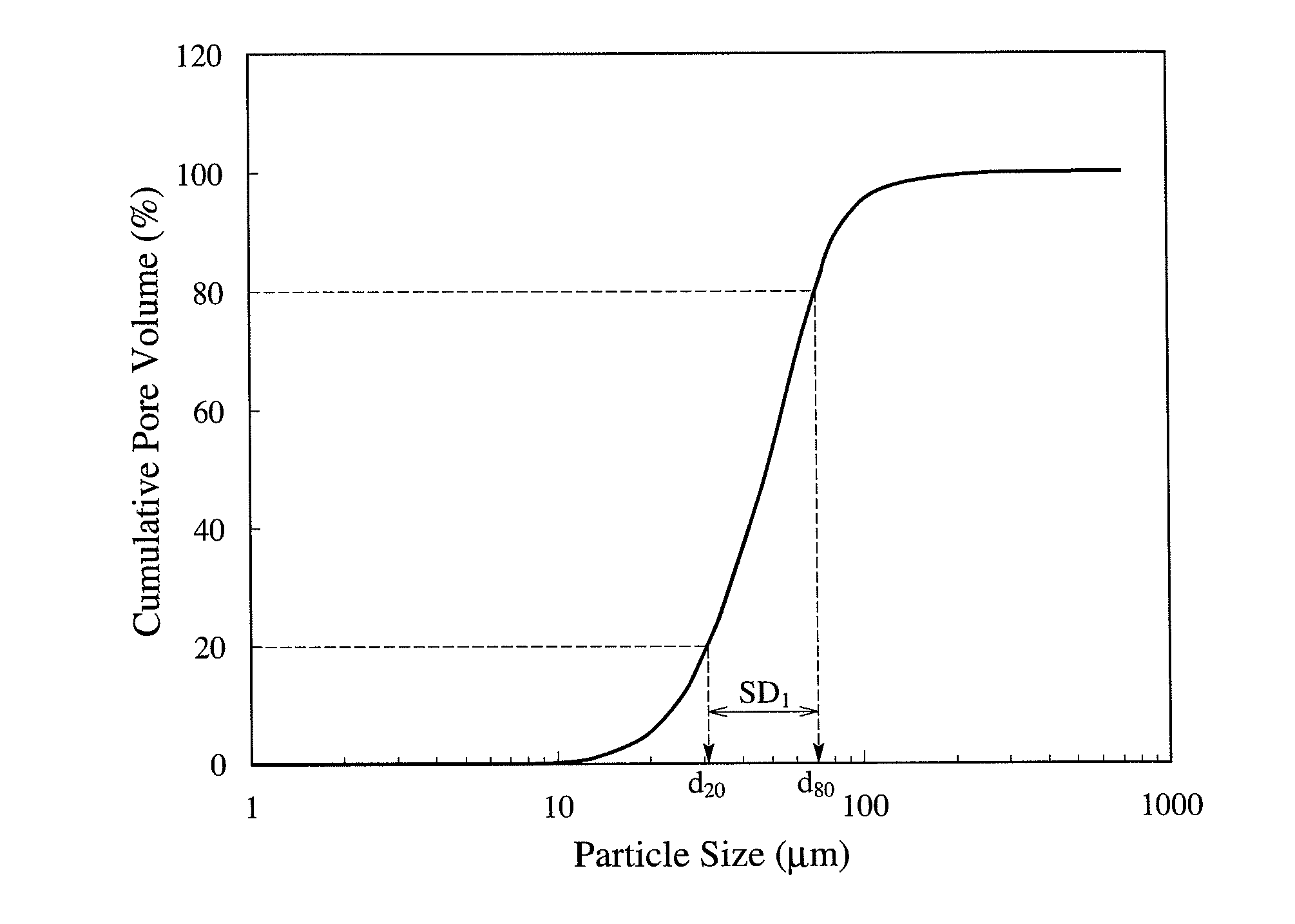
[0063]Starting material powders comprising pulverized amorphous silica (particle size distribution deviation SD1=0.45, mode diameter M50=30.5 μm, the percentage of particles of 200 μm or more=0.9%, the percentage of particles of 100 μm or more=4.0%, the percentage of particles of 20 μm or less=8.5%, roundness=0.4, and containing 0.005% by mass of CaO+Na2O+K2O as impurities), kaolin (average particle size=3.0 μm, and containing 0.32% by mass of CaO+Na2O+K2O as impurities), talc (average particle size=12 μm, and containing 0.5% by mass of CaO+Na2O+K2O as impurities), alumina (average particle size=4.2 μm, and containing 0.3% by mass of CaO+Na2O+K2O as impurities), aluminum hydroxide (average particle size=1.8 μm, and containing 0.05% by mass of CaO+Na2O+K2O as impurities) were mixed in the amounts shown in Table 1, to form a cordierite-forming material powder. This cordierite-forming material powder was dry-mixed with a pore-forming material of a foamed resin having a particle size di...

examples 8-17

, and Comparative Examples 1-4 and 8

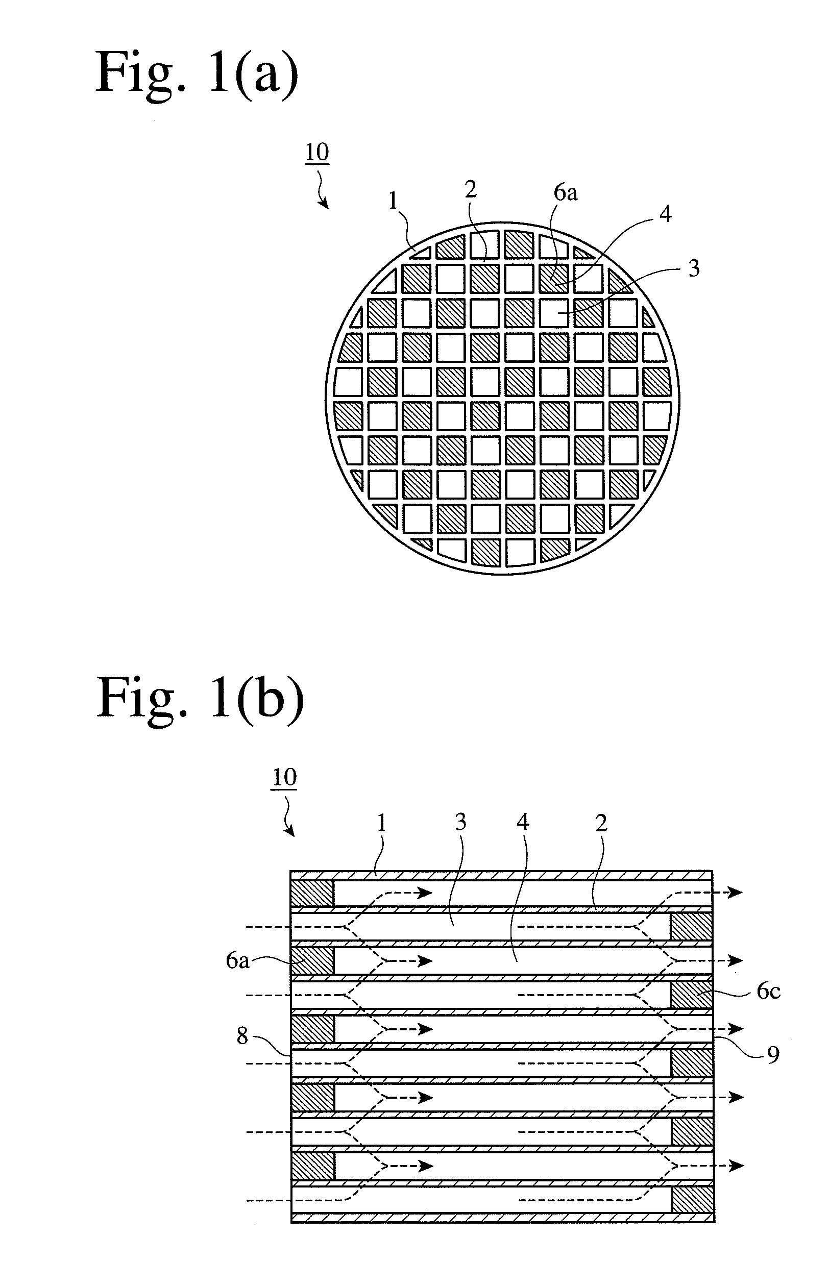
[0066]Using spherical, amorphous silica powder obtained by ejecting finely pulverized, high-purity, natural silica stones into high-temperature flame, whose particle characteristics are shown in Table 1, in the amount shown in Table 1, two ceramic honeycomb structures of 267 mm in outer diameter, 304 mm in length, 1.57 mm in cell wall pitch and 0.3 mm in cell wall thickness were produced in each of Examples 8-17 and Comparative Examples 1-4 and 8, in the same manner as in Example 1 except for changing the amounts of talc powder, silica powder, kaolin powder, alumina powder and aluminum hydroxide powder, and the particle characteristics and amount of the pore-forming material as shown in Table 1. The particle size distribution of silica used in Example 11 is shown in FIG. 4.

[0067]The flow path ends of each ceramic honeycomb structure were alternately plugged with a plugging slurry comprising a cordierite-forming material, dried and sintered to prod...


PUM

PropertyMeasurementUnit
pore size distributionaaaaaaaaaa
pore sizeaaaaaaaaaa
porosityaaaaaaaaaa

Abstract

A cordierite-based ceramic honeycomb filter comprising a honeycomb structure having a large number of flow paths partitioned by porous cell walls, and plugs alternately formed in said flow paths on the exhaust-gas-inlet side or the exhaust-gas-outlet side for permitting an exhaust gas to pass through said porous cell walls to remove particulate matter from the exhaust gas, said porous cell walls having porosity of 45-58%, an average pore size of 15-30 μm, the volume of pores having pore sizes exceeding 50 μm being more than 10% and 25% or less of the total pore volume, the volume of pores having pore sizes of 100 μm or more being 1-8% of the total pore volume, the volume of pores having pore sizes of less than 10 μm being 3-10% of the total pore volume, and said pores having a pore size distribution deviation σ [=log(D20)−log(D80)] of 0.6 or less, wherein D20 represents a pore size (μm) at a pore volume corresponding to 20% of the total pore volume, and D80 represents a pore size (μm) at a pore volume corresponding to 80% of the total pore volume, both in a curve representing the relation between the pore size and the cumulative pore volume, and D80<D20.

Description

CROSS REFERENCE TO RELATED APPLICATIONS[0001]This application is a National Stage of International Application No. PCT / JP2008 / 068605 filed Oct. 14, 2008, claiming priority based on Japanese Patent Application No. 2007-267119 filed Oct. 12, 2007, the contents of all of which are incorporated herein by reference in their entirety.FIELD OF THE INVENTION[0002]The present invention relates to a cordierite-based ceramic honeycomb filter for removing particulate matter from exhaust gases discharged from diesel engines.BACKGROUND OF THE INVENTION[0003]Exhaust gases from diesel engines contain particulate matter (PM) based on carbonaceous soot and SOFs (soluble organic fractions) of high-boiling-point hydrocarbons, and the release of PM into the atmosphere is likely to exert adverse effects on humans and environment. Exhaust pipes connected to diesel engines are thus conventionally provided with ceramic honeycomb filters (simply called “honeycomb filters” below) for capturing PM.[0004]FIGS. ...

Claims


Application Information

Patent Timeline
Patent Type & Authority Patents(United States)
IPC IPC(8): B01D39/14B01D50/00B01D24/00B01D39/06F01N3/00
CPCB01D46/2429C04B35/195C04B35/62665C04B38/0006C04B38/0054C04B38/007C04B38/0074B01D46/2425B01D2046/2433B01D2046/2437B01D2046/2496B01D2275/30C04B2111/00793C04B2235/3201C04B2235/3208C04B2235/3217C04B2235/3218C04B2235/3418C04B2235/3445C04B2235/349C04B2235/528C04B2235/5296C04B2235/5436C04B2235/5481C04B2235/72F01N3/0222B01D46/24492B01D46/24491B01D46/2498B01D46/24493
Inventor OKAZAKI, SHUNJIISHIZAWA, TOSHITAKA
Owner HITACHI METALS LTD
Why Eureka
Try Eureka