Multi-flame lighter
A lighter and multi-flame technology, applied in the direction of combustion ignition, igniter with fuel, combustion method, etc., can solve the problems of weak flame strength, complex lighter structure, high manufacturing cost, etc., achieve uniform fire point and improve atomization effect , The effect of uniform and stable flame
- Summary
- Abstract
- Description
- Claims
- Application Information
AI Technical Summary
Problems solved by technology
Method used
Image
Examples
Embodiment 1
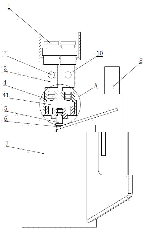
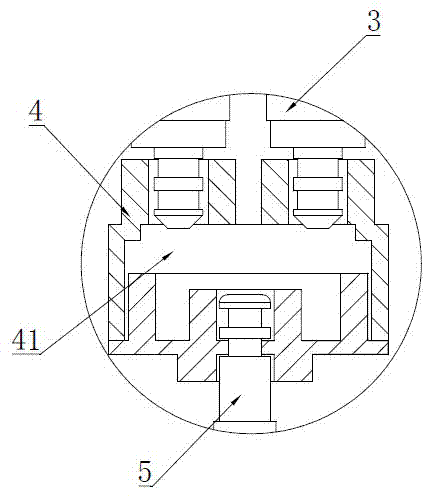
[0021] Depend on Figure 1-3 As shown, the multi-flame lighter includes a housing in which a flame assembly 10, a toggle lever 6, an ignition device 8, and a gas storage box 7 with an outlet valve 5 are provided. The flame assembly 10 includes a flame jet Nozzle 1, air supply pipeline 3 and air inlet 2 arranged on the air supply pipeline 3, said flame assembly 10 is provided with at least two groups, said flame assembly 10 and air outlet valve 5 are hermetically connected with flow divider 4 , the inside of the splitter 4 is provided with a gas atomization chamber 43 , and the upper end is provided with an air outlet 41 connected to the gas supply pipeline 3 , and the lower end is provided with an air inlet 42 connected with the air outlet valve 5 . The ignition device can be an electric spark device such as a flint and grinding wheel assembly, an electronic igniter, etc. The ignition device is manually pressed to release the electric spark, and at the same time, the lever is ...
Embodiment 2
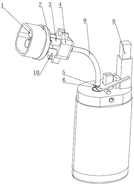
[0025] Depend on Figure 4-6 As shown, the multi-flame lighter includes a housing in which a flame assembly 10, a toggle lever 6, an ignition device 8, and a gas storage box 7 with an outlet valve 5 are provided. The flame assembly 10 includes a flame jet Nozzle 1, air supply pipeline 3 and air inlet 2 arranged on the air supply pipeline 3, said flame assembly 10 is provided with at least two groups, said flame assembly 10 and air outlet valve 5 are hermetically connected with flow divider 4 , the gas atomization cavity 43 is arranged inside the flow divider 4 , and the gas outlet 41 connected with the gas supply pipeline 3 is arranged at the upper end, and the gas inlet 42 connected with the gas outlet valve 5 is arranged at the lower end. An air outlet hose 9 is connected between the air outlet valve 5 and the air inlet 42 . The additional gas outlet hose can adjust the direction and angle of the flame nozzle arbitrarily. The gas can be evenly distributed to each flame com...
PUM
 Abstract
Description
Claims
Application Information
 - R&D
- Intellectual Property
- Life Sciences
- Materials
- Tech Scout
- Unparalleled Data Quality
- Higher Quality Content
- 60% Fewer Hallucinations
Browse by: Latest US Patents, China's latest patents, Technical Efficacy Thesaurus, Application Domain, Technology Topic, Popular Technical Reports.
© 2025 PatSnap. All rights reserved.Legal|Privacy policy|Modern Slavery Act Transparency Statement|Sitemap|About US| Contact US: help@patsnap.com


