Thermal bulb of thermal expansion valve, filling method thereof and refrigerating system with same

A technology of thermal expansion valve and refrigeration system, which is applied in the direction of material expansion/contraction thermometers, refrigerators, refrigeration components, etc., which can solve the problems of high superheat, large change of static superheat, and low energy efficiency ratio of refrigeration systems. Achieve high energy efficiency ratio and small change in superheat

Inactive Publication Date: 2014-01-01
ZHEJIANG SANHUA CLIMATE & APPLIANCE CONTROLS GRP CO LTD
View PDF9 Cites 4 Cited by
  • Summary
  • Abstract
  • Description
  • Claims
  • Application Information

AI Technical Summary

Benefits of technology

This patented technology improves upon existing systems by adding an element called Thermal Expansion Valve (TXV) that can detect changes in pressure or other factors related to how well heat exchangers work effectively at different temperatures. By filling it with these elements, there are fewer ways to adjust their operation based on changing conditions like ambient air levels or coolant flow rates. Overall, this innovative design enhances the performance of both conventional and new types of refrigansystems.

Problems solved by technology

This patented technical problem addressed in this patents relates to improving the operation of thermostatic expanders in refrigansystems such as an air conditioner due to their high cost compared to other alternatives like natural gas. Additionally, current methods are either too complicated or require expensive materials, which makes it difficult to use these options effectively without sacrifices on its overall economic benefit.

Method used


Image

  • Thermal bulb of thermal expansion valve, filling method thereof and refrigerating system with same
  • Thermal bulb of thermal expansion valve, filling method thereof and refrigerating system with same
  • Thermal bulb of thermal expansion valve, filling method thereof and refrigerating system with same

Examples


Embodiment 1

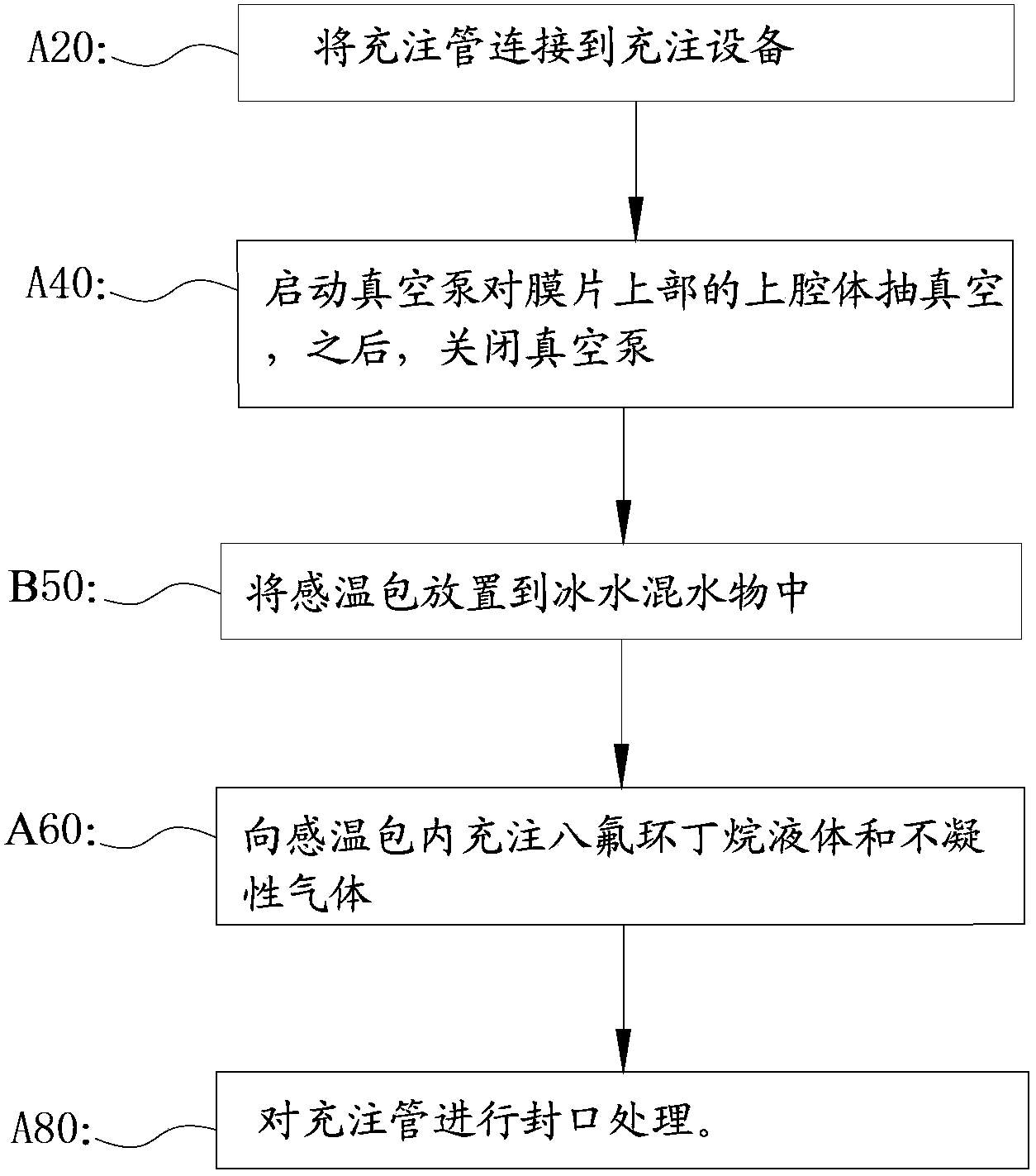
[0031] Such as figure 2 It is a flow chart of the first specific embodiment of the filling method of the temperature sensing bulb of the present invention. The filling method of the temperature-sensing bulb of the thermal expansion valve of the present embodiment 1 comprises the following steps:

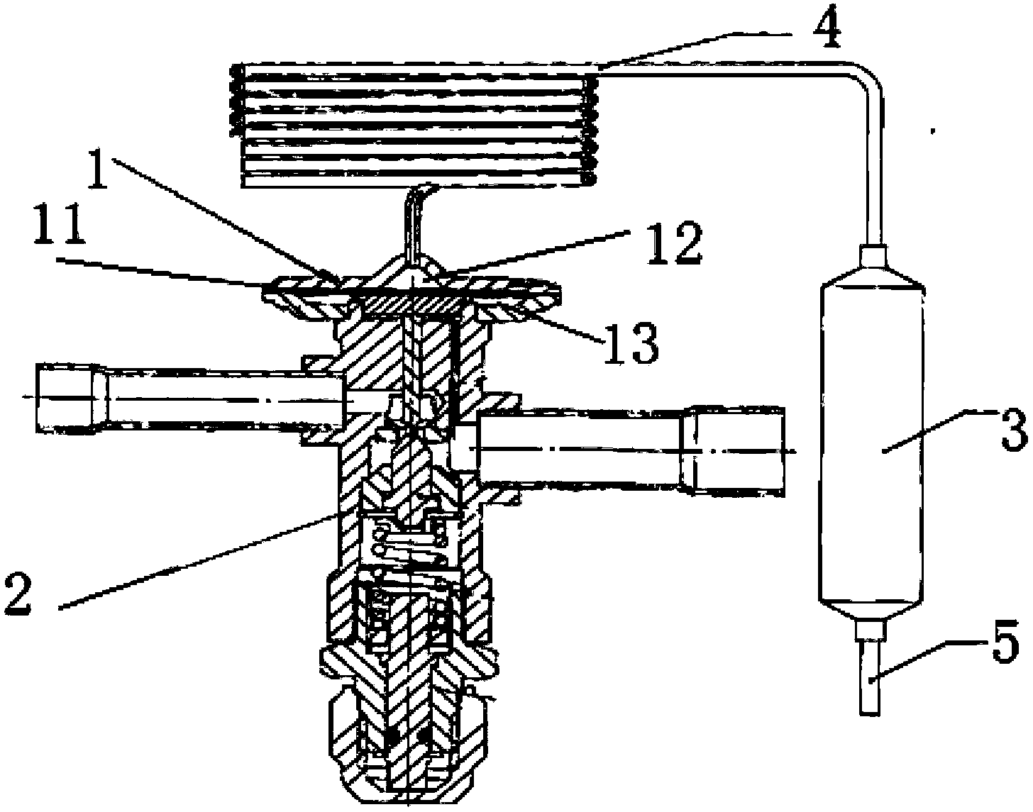
[0032] A20: At room temperature, connect the filling tube 5 to the filling equipment;

[0033] A40: Start the vacuum pump to evacuate the upper cavity 12 above the diaphragm 11 to below -0.095MPa, and then turn off the vacuum pump;

[0034] A50: Put the temperature-sensing package 3 into the ice-water mixture to keep the ambient temperature of the temperature-sensing package 3 at zero degrees.

[0035] A60: Fill the temperature sensing bulb 3 with octafluorocyclobutane liquid and non-condensable gas. Specifically, first fill a certain weight of liquid octafluorocyclobutane into the temperature-sensitive package 3, and then fill a certain pressure of non-condensable gas into the t...

Embodiment 2

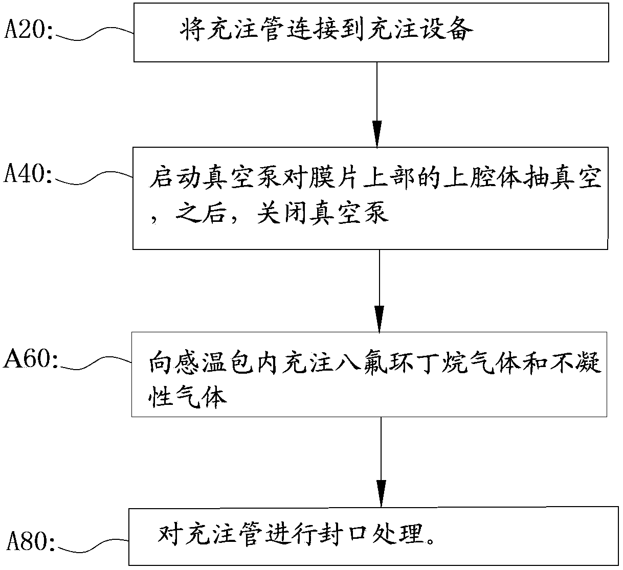
[0038] Such as image 3 It is a flow chart of the second specific embodiment of the filling method of the temperature sensing bulb of the present invention. The filling method of the temperature-sensing bulb of the thermal expansion valve in the second embodiment specifically includes the following steps:

[0039] A20: At room temperature, connect the filling tube 5 to the filling equipment;

[0040] A40: Start the vacuum pump to evacuate the cavity above the diaphragm to below -0.095MPa, then turn off the vacuum pump;

[0041] A60: Fill the temperature sensing bag 3 with octafluorocyclobutane gas and non-condensable gas. Specifically, octafluorocyclobutane at a certain pressure is filled into the temperature sensing bulb 3 first, and then non-condensable gas at a certain pressure is filled into the temperature sensing bulb 3 .

[0042] A80: Seal the filling tube 5 .


PUM


Abstract

The invention discloses a thermal bulb of a thermal expansion valve, a filling method of the thermal bulb and a refrigerating system with the thermal bulb of the thermal expansion valve. The thermal expansion valve comprises a valve body component, a driving component and the thermal bulb, wherein the driving component is used for driving the valve body component, and the thermal bulb is filled with thermal working media. The thermal bulb is characterized in that the thermal working media comprise octafluorocyclobutane and non-condensable gas. The filling method of the thermal bulb includes the steps of A20, enabling a filling tube to be connected to a filling device, A40, starting a vacuum pump to vacuumize a cavity on a membrane, and then stopping the vacuum pump, A60, filling the thermal bulb with the octafluorocyclobutane and the non-condensable gas, and A80, carrying out sealing processing on the filling tube. After the thermal bulb and the filling method of the thermal bulb are used, fluctuations of static superheat degrees of the thermal expansion valve at different thermal bulb temperatures are quite small, and the refrigerating system with the thermal expansion valve is high in energy efficiency ratio.

Description


Claims


Application Information

Patent Timeline
Owner ZHEJIANG SANHUA CLIMATE & APPLIANCE CONTROLS GRP CO LTD
Why Eureka
Try Eureka