Roll ball high-speed electronic spindle

A high-speed motorized spindle and ball technology, used in clamping, support, positioning devices, etc., can solve the problems of lowering the spindle temperature, low speed of the ball motorized spindle, single structure, etc., and achieve the effect of satisfying high speed

Active Publication Date: 2012-09-05
GUANGZHOU HAOZHI ELECTROMECHANICAL
View PDF5 Cites 1 Cited by
  • Summary
  • Abstract
  • Description
  • Claims
  • Application Information

AI Technical Summary

Problems solved by technology

[0002] In the prior art, the body of the ball electric spindle is mainly used to fix and install bearings, bearing housings, stators and other components, but as the shell of the spindle, it often cannot protect the normal operation of each component, especially for high-speed ball spindles. No circulating cooling system can be provided to reduce the temperature of the spindle when it is working
The aluminum water jacket assembly for the ball high-speed electric spindle has a complex structure, which is not conducive to the heat dissipation of the spindle, inconvenient installation, single function, and difficult to grasp the assembly accuracy
The air cylinder in the pneumatic tool unloading mechanism for the ball high-speed electric spindle has a complex structure, low sealing performance, and unstable transmission. Frequent tool changes are easy to damage or leak air.
Bearing housing components for ball high-speed electric spindles have a single structure, difficult processing, inconvenient assembly and disassembly, difficult adjustment of axial stability, and low heat dissipation
The through-hole structure of the shaft core for the ball high-speed electric spindle is unreasonable, which makes it inconvenient to assemble the tie rod and other accessories. Short life, frequent replacement and other shortcomings, so today's ball electric spindle speed is not high, and the service life is not long

Method used


Image

  • Roll ball high-speed electronic spindle
  • Roll ball high-speed electronic spindle
  • Roll ball high-speed electronic spindle

Examples


Embodiment 1

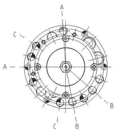
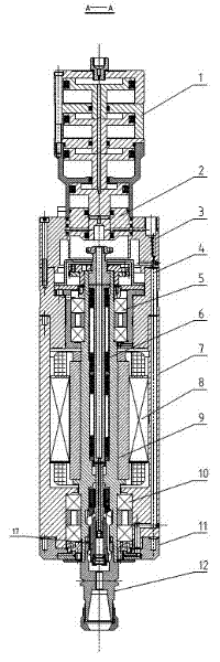
[0062] Such as Figure 1 to Figure 30 As shown in each figure, the opening of the upper part of the body 7 of the present invention is connected and fixed with a bearing block assembly 4, and the middle through hole of the bearing block assembly 4 is fixed with an upper bearing assembly 5, and the lower part of the upper bearing assembly 5 is provided with a stator 8. The lower cavity of 7 is provided with a lower bearing assembly 10, the lower part of the lower bearing assembly 10 is fixed with the lower cover assembly 11 of the body, and the bottom of the lower cover assembly 11 of the body is fixed with a dust cover 13; the upper part of the bearing seat assembly 4 is fixed with an aluminum water jacket Component 3, the opening of the upper cavity of the aluminum water jacket component 3 is fixed with an air guide plug 2, the upper part of the air guide plug 2 is fixed with a knife unloading cylinder 1, and there is a shaft core component 9 below the bottom piston of the kni...

Embodiment 2

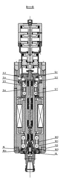
[0064] Same as Embodiment 1, except that the contact surface between the air guide plug 2 and the inner wall of the aluminum water jacket assembly 3 is provided with an O-shaped sealing ring, and the contact surface between the air guide plug 2 and the bottommost piston of the unloading cylinder 1 All are provided with a star-shaped sealing ring; the knife unloading cylinder 1 includes a cylinder top cover 1.1, the middle part of the cylinder top cover 1.1 is provided with an intake pipeline connection screw hole 1.8, the first stage piston 1.2 at the bottom of the cylinder top cover 1.1, and the second stage piston 1.11, third-stage piston 1.13, segmented piston 1.6, first-stage cylinder 1.3, second-stage cylinder 1.12, lowest-stage cylinder 1.4, the contact points between the first-stage, second-stage and third-stage pistons and all stages of cylinders are uniform A sealing ring 1.10 is provided, locking screws 1.9 are provided on the inner walls between the cylinders at all ...

Embodiment 3

[0066] Same as Embodiment 1, except that the aluminum water jacket assembly 3 includes an aluminum water jacket bearing seat 3.3, a protruding sealing ring 3.4 of the aluminum water jacket bearing seat 3.3, and an axial The through piston hole 3.2, the inner wall of the piston hole 3.2 is provided with a piston sealing ring 3.6, the positioning step 3.8 at the bottom of the aluminum water jacket bearing seat 3.3, the aluminum water jacket inner cavity 3.7 inside the aluminum water jacket bearing seat 3.3, the aluminum water jacket bearing seat The outer ring wall on 3.3 also includes cylinder broach hole 3.1, knife unloading dust blowing hole 3.5, coolant inlet and outlet hole 3.9, lubricating oil recovery hole 3.10, upper bearing lubricating oil inlet hole 3.11, power cord installation hole 3.12, cylinder Install connection hole 3.13, ground wire connection position 3.14, air seal hole 3.15, lower bearing lubricating oil inlet hole 3.16 and aluminum water jacket installation h...


PUM


Abstract

The invention relates to a roll ball high-speed electronic spindle, and in particular relates to a roll ball high-speed electronic spindle for mechanical processing of a machine tool. The roll ball high-speed electronic spindle in the invention is a mechanical-electrical integration assembly integrating a rolling bearing, a cooling device, an automatic tool changing system and a motor drive device. The roll ball high-speed electronic spindle has the advantage that the working number of revolutions can reach 40000rpm, has high accuracy, large torque and long service life, and is convenient to popularize and apply.

Description

technical field [0001] The invention relates to a machining equipment, in particular to a high-speed electric spindle for machining machine tool balls. Background technique [0002] In the prior art, the body of the ball electric spindle is mainly used to fix and install bearings, bearing housings, stators and other components, but as the shell of the spindle, it often cannot protect the normal operation of each component, especially for high-speed ball spindles. A circulating cooling system cannot be provided to reduce the temperature of the spindle when it is working. The aluminum water jacket assembly for the ball high-speed electric spindle has a complex structure, which is not conducive to the heat dissipation of the spindle, inconvenient installation, single function, and difficult to grasp the assembly accuracy. The air cylinder in the pneumatic tool unloading mechanism for the ball high-speed electric spindle has a complex structure, low sealing performance, and uns...

Claims


Application Information

Patent Timeline
Patent Type & Authority Patents(China)
IPC IPC(8): B23Q3/12B23B19/02B23Q11/00B23Q11/12
Inventor 汤秀清
Owner GUANGZHOU HAOZHI ELECTROMECHANICAL
Why Eureka
Try Eureka