Automatic change-over switch for two power sources

An automatic transfer switch and dual power supply technology, which is applied in the direction of electric switches, circuits, and electrical components, can solve the problems of complex and clumsy push-and-swing components, stuck actuators, and high cost of use, so as to prevent line aging or assembly errors, and the overall Compact structure and easy installation

Active Publication Date: 2014-01-01
张韶松 +1
View PDF4 Cites 8 Cited by
  • Summary
  • Abstract
  • Description
  • Claims
  • Application Information

AI Technical Summary

Problems solved by technology

Due to the complexity and clumsiness of the push-and-swing components, not only a large-power motor is required, but also various accessories such as metal brackets, brackets, fixed slide bars, and push-and-swing top plates are required for its operation, so that the overall mechanical actuator is not only complicated, but also expensive to use. High, and due to the coordinated operation of various accessories, it brings more uncertain operational risks to the execution process. For example, a problem with a certain accessory causes the actuator to be stuck and the emergency power supply cannot be switched.
[0005] Because it is an industrial product, at present, the environment where the dual-power automatic transfer switch is used is often airtight, unventilated, humid, etc., and the CB-level dual-power automatic transfer switch in the prior art has not adopted either the control circuit board, the actuator or the circuit breaker. Relatively tight sealing measures, in this harsh environment, the key components are prone to aging and corrosion, which greatly reduces the service life and causes use accidents

Method used


Image

  • Automatic change-over switch for two power sources
  • Automatic change-over switch for two power sources
  • Automatic change-over switch for two power sources

Examples


Embodiment Construction

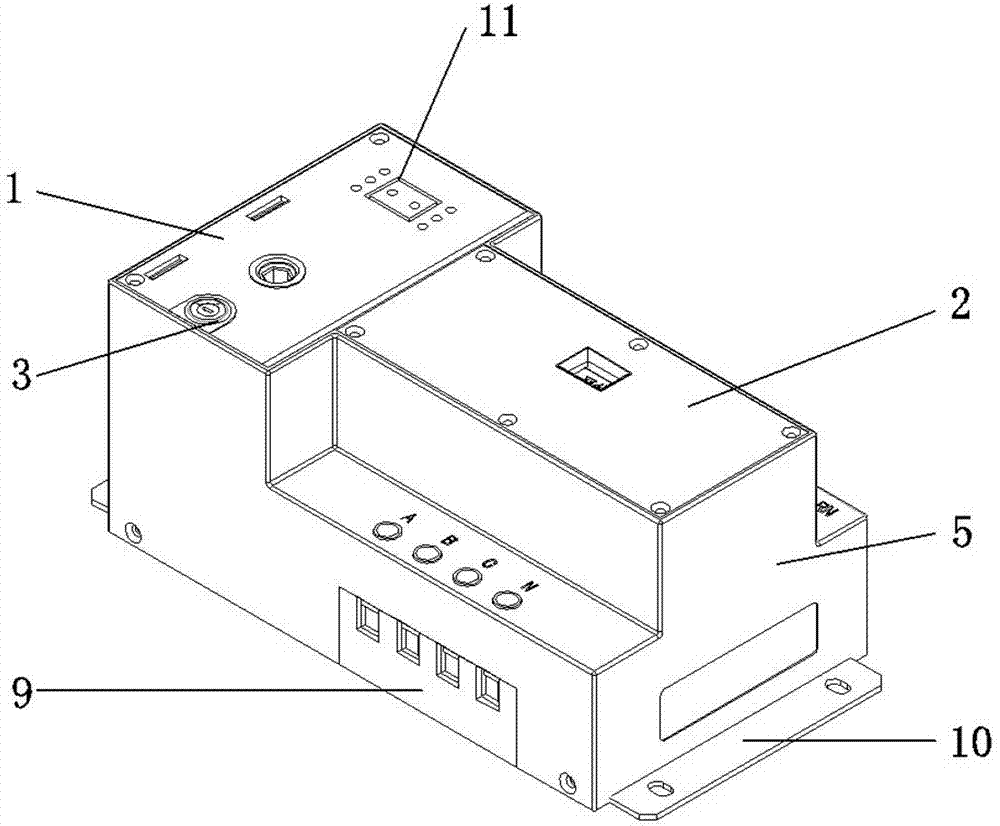
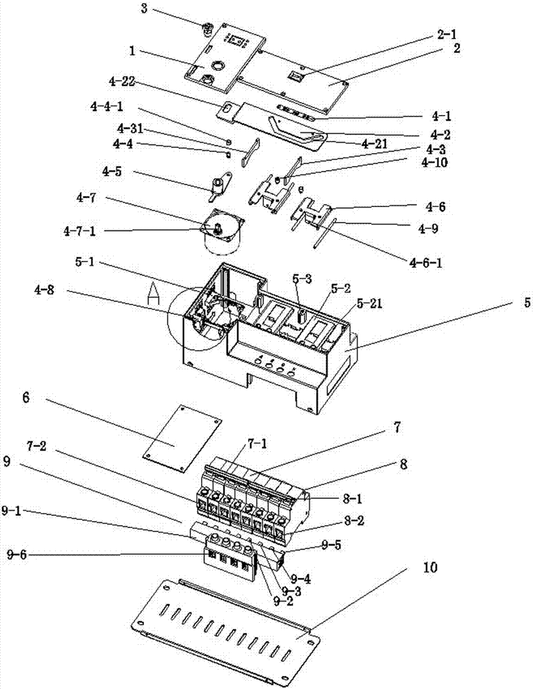
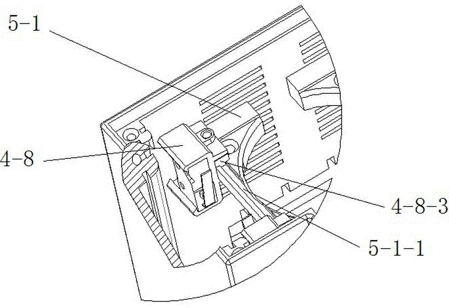
[0034]As shown in Figures 1 to 17, the dual-power automatic transfer switch includes a control circuit board 6, a main circuit breaker 7, a backup circuit breaker 8, a controller cover 1, and a circuit breaker with a closing position indication window 2-1 Cover 2, isolation electric lock 3, actuator, installation base 5, bus bar device 9, installation base plate 10.

[0035] Drive turntable 4-5 comprises turntable core 4-5-1, turntable shaft 4-5-2, turntable core 4-5-1 is a tubular body, one end center hole is hexagonal hole 4-5-13, the other end center hole It is a rectangular hole 4-5-11 with both ends being arc-shaped, and four arc-shaped protrusions 4-5-12 are arranged at intervals on the end surface of the tube wall at one end of the turntable core 4-5-1; the turntable shaft 4- 5-2 One end is a conical plate-shaped body, the other end is a rectangular pendulum 4-5-21 with an arc-shaped head, and an instrument hole 4-5-22 and one and four The petal holes 4-5-23 matched by...


PUM


Abstract

The invention relates to an automatic change-over switch for two power sources. The automatic change-over switch comprises a control circuit board, a main breaker, an auxiliary breaker and a busbar device into which an A-phase copper bar, a B-phase copper bar, a C-phase copper bar and an N-phase copper bar are inserted in a connecting mode, wherein the busbar device is fixed inside an installation base. Two adjusters at the switching-on positions and a motor are fixed on a motor bracket, a driving rotary table to which an instrument part is connected in a riveting mode is clamped to a rotating shaft of the motor, two sliding arm guiding blocks are inserted to two pairs of inserting grooves of the sliding arm guiding blocks respectively, four sliding block sliding guiding rods are placed on two sliding block brackets respectively, and each sliding block bracket is provided with a sliding block in a buckling mode, wherein guiding columns are fixed on the sliding blocks. Sliding arms are placed on the two sliding arm guiding blocks and the two sliding blocks, the instrument part is arranged in rectangular holes of the sliding arms, the two guiding columns are arranged inside V-shaped strip holes of sliding arm faces, a mechanical switching-on indicator is fixed on the faces of the sliding arms, and a controller cover, a breaker cover and an installation bottom plate are fixed on the front face and the bottom face of the installation base respectively, wherein the controller cover is provided with an isolation electric lock. The automatic change-over switch has the advantages of being compact in overall structure, high in protection level, reliable and low in cost.

Description

technical field [0001] The invention relates to an electric appliance control switch device, in particular to a double power supply automatic transfer switch. It is suitable for industrial and mining enterprises, institutions, schools, hospitals, shopping malls, banks, communications and high-rise buildings and other important places where power failure is not allowed. Background technique [0002] Many industries and departments have very high requirements on the reliability of power supply. In order to ensure the continuity of power supply, many important occasions have adopted dual power automatic transfer switches to power electrical appliances. As an essential device for power switching, its main function is that when the normal power supply fails, it can automatically switch to the backup power supply to continue supplying power to the load, and it can automatically perform reverse switching after the power supply returns to normal, so as to meet the requirements of th...

Claims


Application Information

Patent Timeline
Patent Type & Authority Applications(China)
IPC IPC(8): H01H9/00H01H9/02H01H9/26
Inventor 张韶松郑晓欧
Owner 张韶松
Why Eureka
Try Eureka