Brake system for a motor vehicle and method for operating the brake system

A technology of braking equipment and motor vehicles, which is applied in the direction of braking action starting device, braking transmission device, hydraulic braking transmission device, etc.

Active Publication Date: 2016-08-31
CONTINENTAL AUTOMOTIVE TECH GMBH
View PDF5 Cites 0 Cited by
  • Summary
  • Abstract
  • Description
  • Claims
  • Application Information

AI Technical Summary

Problems solved by technology

It is considered disadvantageous in the previously known braking system that, in the event of failure of the control or drive of the electrically controllable pressure supply device, a high brake pedal force has to be applied by the driver in order to achieve a sufficient movement braking deceleration

Method used


Image

  • Brake system for a motor vehicle and method for operating the brake system
  • Brake system for a motor vehicle and method for operating the brake system
  • Brake system for a motor vehicle and method for operating the brake system

Examples


Embodiment Construction

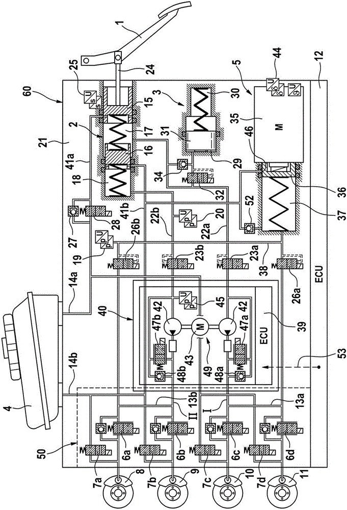
[0036] figure 1 A first embodiment of the brake system according to the invention is schematically shown in . The brake system basically comprises a hydraulic operating unit 2 that can be operated by means of an operating pedal or brake pedal 1 , a travel simulator or simulation device 3 that interacts with the hydraulic operating unit 2 , and a position corresponding to the hydraulic operating unit 2 . Pressure medium storage container 4 at atmospheric pressure, first electrically controllable pressure supply device 5 , second electrically controllable pressure supply device 49 , electronic control and regulation unit 12 and electrically controllable pressure modulation device 50 .

[0037] The pressure modulation device 50 comprises, for example, for each wheel brake 8 , 9 , 10 , 11 of a motor vehicle (not shown) an inlet valve 6 a - 6 d and an outlet valve 7 a - 7 d which are arranged in pairs They are hydraulically connected together via intermediate connections and to th...


PUM


Abstract

The invention relates to a brake system for a motor vehicle and a method for operating the brake system, said brake system having: a main brake cylinder (2) in two Brake circuits (I, II) with wheel brakes (8, 9, 10, 11) are respectively connectable or connected to the pressure chambers; for each brake circuit (I, II) there is an electrically operable separate valves (23a, 23b) for separating said pressure chambers (17, 18) from said brake circuits; electrically controllable first pressure supply means (5); for each brake circuit (I, II ) each electrically operable sequence valve (26a, 26b) for hydraulically connecting said first pressure supply device (5) to said brake circuit; Simulation device (3) for the hydraulic connection of at least one pressure chamber (17) of the master brake cylinder (2), wherein an electrically controllable second pressure supply device (49, 149) is provided, said second pressure supply device There is at least one suction connection and a pressure connection, the suction connection of the second pressure supply device being connected or connectable to one of the pressure chambers (17, 18), the pressure connection of the second pressure supply device being connected to The brake circuits (I, II) belonging to this pressure chamber can be connected or linked together.

Description

technical field [0001] The invention relates to a brake system for a motor vehicle according to the preamble of claim 1 and to a method for operating such a brake system. Background technique [0002] Hydraulic vehicle braking systems are known which are designed as external braking systems and in addition to a muscularly actuated main brake which is hydraulically connected to the wheel brakes and provides pressure and volume for actuating the wheel brakes In addition to the cylinders, further electrically controllable pressure and volume supply devices are included, which actuate the wheel brakes in the "brake-by-wire" operating mode. In the event of failure of the electrically controllable pressure and volume supply device, the wheel brakes are actuated solely by the muscular force of the driver of the vehicle (non-reinforced backup mode of operation). [0003] An electrohydraulic brake system is known from WO 2011 / 029812 A1 with a brake pedal actuatable master brake cyli...

Claims


Application Information

Patent Timeline
Patent Type & Authority Patents(China)
IPC IPC(8): B60T8/40B60T8/44
CPCB60T8/4081B60T8/442B60T13/745B60T13/686B60T8/4072B60T7/042B60T7/12B60T13/161B60T13/62B60T8/40B60T8/44B60W10/18B60T11/16B60T11/232B60T7/06
Inventor H-J·法伊格尔H·比勒
Owner CONTINENTAL AUTOMOTIVE TECH GMBH
Why Eureka
Try Eureka