
Device for controlling the valve control times of an internal combustion engine

A valve control timing and internal combustion engine technology, applied in mechanical equipment, engine components, machines/engines, etc., can solve the problems of high cost, consumption, and low component strength, and achieve the effects of system power, improved vibration performance, and light weight

Inactive Publication Date: 2013-02-27
SCHAEFFLER TECH AG & CO KG
View PDF11 Cites 0 Cited by
  • Summary
  • Abstract
  • Description
  • Claims
  • Application Information

AI Technical Summary

Problems solved by technology

When using this solution, therefore, the high costs are mostly due to the relatively complex production
[0006] If a solution using plastic is chosen, the component strength is correspondingly lower, despite the use of reinforcing fibers

Method used


Image

  • Device for controlling the valve control times of an internal combustion engine
  • Device for controlling the valve control times of an internal combustion engine
  • Device for controlling the valve control times of an internal combustion engine

Examples


Embodiment Construction

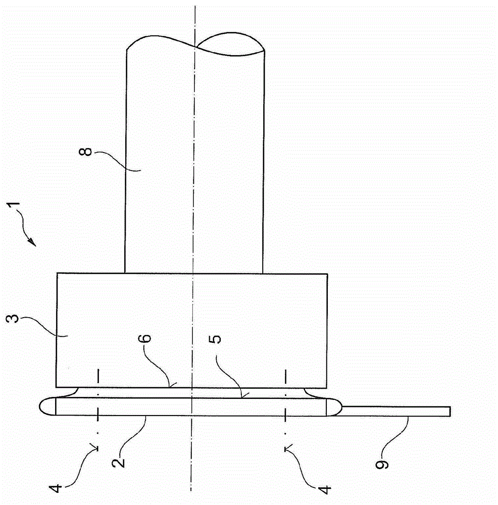
[0025] figure 1 A camshaft adjuster 1 of an internal combustion engine is schematically shown in FIG. The camshaft adjuster 1 is used in a known manner to adjust the inner rotor connected to the camshaft 8 of the internal combustion engine relative to the stator 3 by means of a generally hydraulically actuated (not shown) impeller, so that it is possible between the "advance stop" and the " Hysteresis stop" to adjust. The stator 3 is referred to here as an additional component.

[0026] The camshaft adjuster 1 has a drive element 2 in the form of a toothed pulley driven by the crankshaft of the internal combustion engine by means of a belt 9 . The drive element 2 is screwed to the add-on part 3 using a screw connection 4 for this purpose. The stator 3 is driven by the drive element 2 and rotates about the axis of rotation at the camshaft speed during operation of the internal combustion engine.

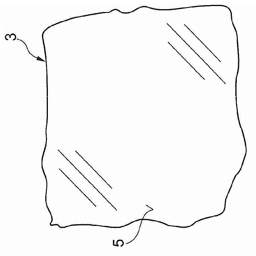
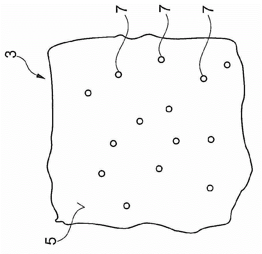
[0027] The additional part 3 has a contact surface 5 for abutting against a c...


PUM


Abstract

The invention relates to a device (1) for controlling and / or influencing the valve control times of an internal combustion engine, in particular to a camshaft adjustment device, which comprises a drive element (2) which is fastened to an attachment part (3) with a screw connection (4), wherein the drive element (2) and / or the attachment part (3) are / is composed of a fibre-reinforced material. In order to obtain a more lightweight design and to be able to reduce screwing forces, the invention provides that at least one of the contact faces (5, 6) between the drive element (2) and the attachment part (3) is at least partially subjected to material-removing processing.

Description

technical field [0001] The invention relates to a device for controlling and / or influencing the valve timing of an internal combustion engine, in particular a camshaft adjustment device, which device comprises a drive element fastened to an additional part by means of a screw connection, wherein the drive element and / or the additional part Made of fiber reinforced raw material. Background technique [0002] A device of this type is known, for example, from EP 1 485 580 B1. A drive device for valve train control of a vehicle is described here, wherein in particular a camshaft adjusting device is considered. The device has at least one drive wheel and a functional component, in particular a stator of a camshaft adjuster. [0003] It is known to use steel or iron-based sintered raw materials for the necessary components, in particular for sprockets or toothed belt pulleys. A high strength of the component can thus be achieved. This high strength is required in particular at...

Claims


Application Information

Patent Timeline
Patent Type & Authority Applications(China)
IPC IPC(8): F01L1/344
CPCF01L1/3442F01L1/34F01L2101/00B24B1/00F01L2103/00F01L1/344F01L2301/00F01L2303/00
Inventor 安德烈亚斯·舒尔特勒妮·君特安德烈亚斯·施特劳斯
Owner SCHAEFFLER TECH AG & CO KG
Learn More