Infrared sensor systems and methods

A sensor and infrared image technology, applied to TV system components, instruments, alarms, etc., can solve problems such as difficult camera placement

Active Publication Date: 2014-01-01
FLIR SYST INC
View PDF5 Cites 23 Cited by
  • Summary
  • Abstract
  • Description
  • Claims
  • Application Information

AI Technical Summary

Problems solved by technology

In the case of total or partial collapse of a building, traditional visible light cameras may not be

Method used

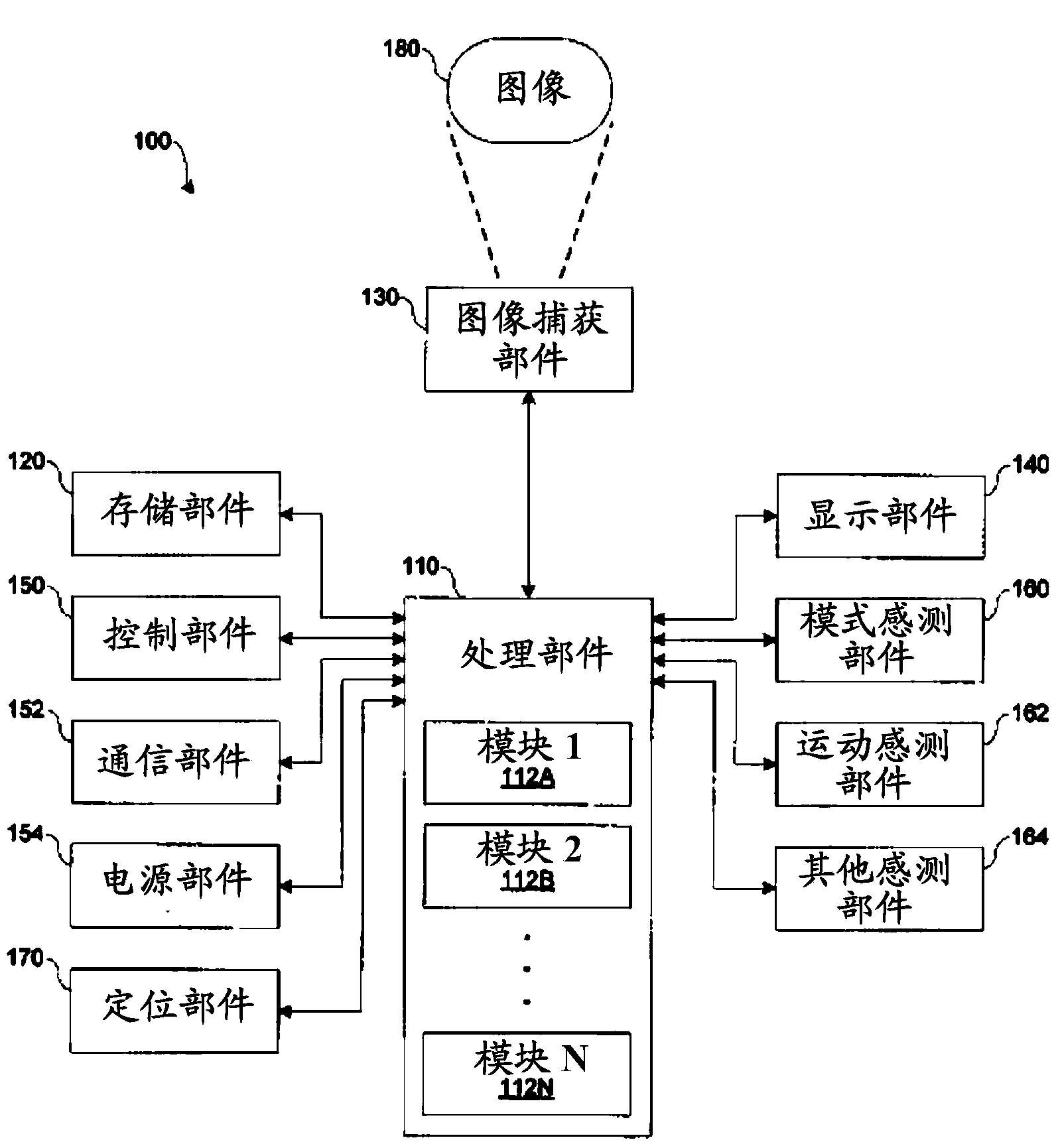
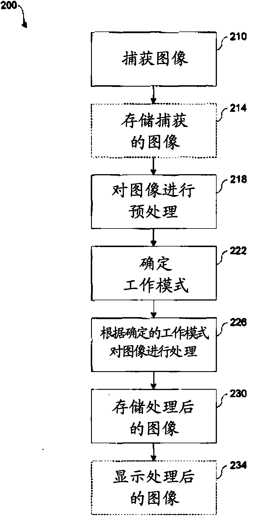
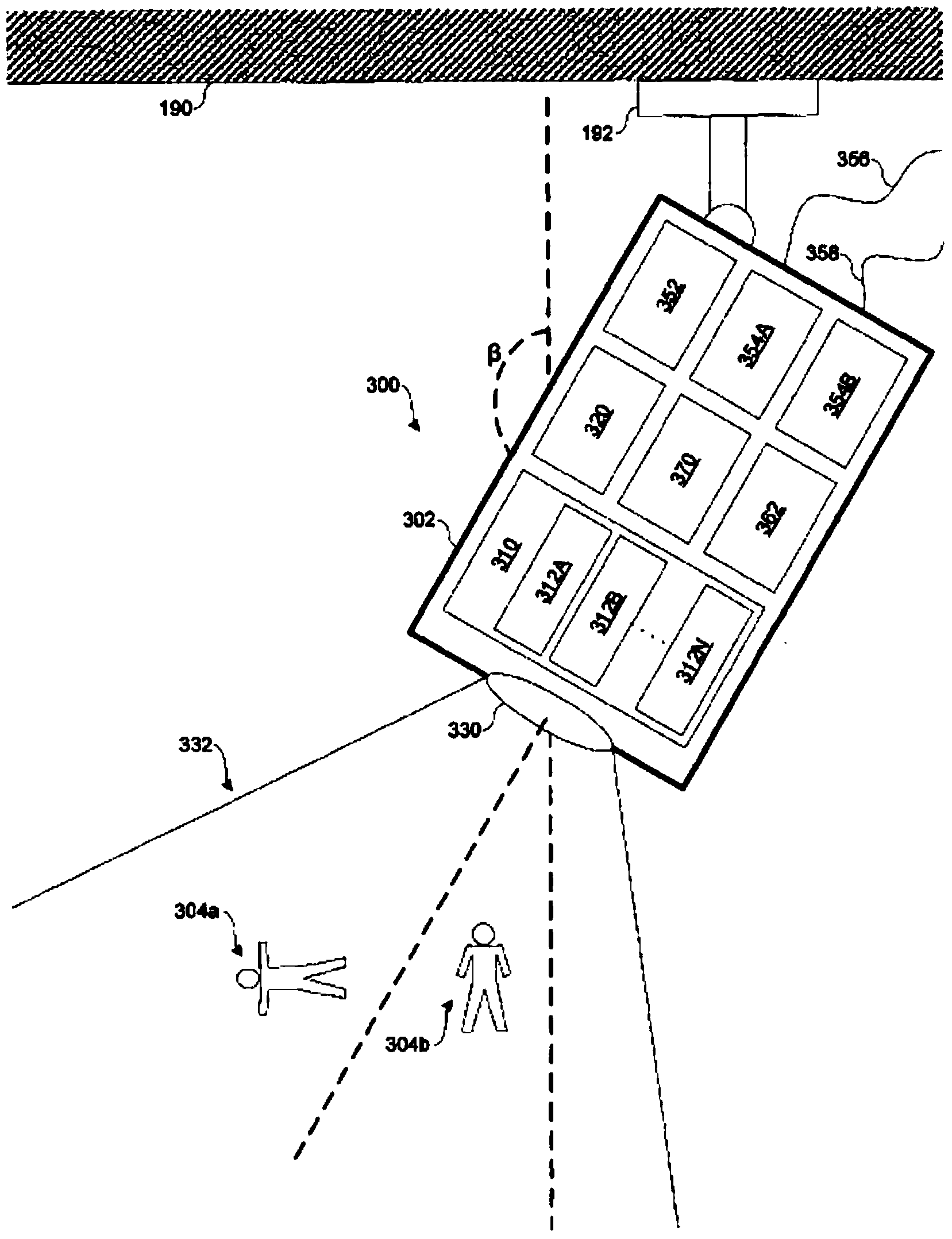

Image

  • Infrared sensor systems and methods
  • Infrared sensor systems and methods
  • Infrared sensor systems and methods

Examples


Embodiment Construction

[0025] In accordance with one or more embodiments, the infrared imaging systems and methods disclosed herein relate to search, rescue, evacuation, remediation, and / or detection of persons who may be , earthquakes, explosions, floods, fires, tornadoes, terrorist attacks, etc.) and damaged buildings. For example, in the event of an emergency or disaster where power may go out, it is critical to quickly search and rescue people to quickly and easily locate people in a structure, building, or other defined area. Even in non-emergency situations, it is important to help someone who has fallen quickly and easily. As examples of structures, it may be necessary to monitor remedial effects (e.g., due to flooding or fire), e.g., to verify the status or completion of remedial effects (e.g., damp has been remediated), and whether further attention is required (e.g. , the fire has reignited, or the potential fire hazard has increased due to an increased thermometer reading).

[0026] In ...


PUM


Abstract

Infrared imaging systems and methods disclosed herein, in accordance with one or more embodiments, provide for an infrared camera system comprising a protective enclosure and an infrared image sensor adapted to capture and provide infrared images of areas of a structure. The infrared camera system includes a processing component adapted to receive the infrared images of the areas of the structure from the infrared image sensor, process the infrared images of the areas of the structure by generating thermal information, and store the thermal information in a memory component for analysis.

Description

[0001] Cross References to Related Applications [0002] This application claims priority from US Provisional Patent Application No. 61 / 445,254, which is hereby incorporated by reference in its entirety. technical field [0003] The present application relates to an infrared imaging system, and more particularly, to an infrared sensor system and method. Background technique [0004] When a building is damaged, for example, during an emergency (e.g., earthquake, explosion, terrorist attack, flood, fire, other type of disaster, etc.), government agencies often attempt to obtain information about the damage and the (e.g., any type of structure or defined area). Surveillance cameras can be used to uncover this information. Surveillance cameras typically use color and monochrome imagers that are sensitive to ambient light in the visible spectrum. Unfortunately, visible light cameras aren't very good at detecting people, including those in need. For example, visible light came...

Claims


Application Information

Patent Timeline
IPC IPC(8): G08B21/04
CPCG08B21/043G08B21/10G08B21/0476G01J5/0025G01J5/10H04N5/33G01J2005/0077
Inventor N·霍根斯特恩M·L·迪尔小A·J·麦高恩J·D·弗兰克A·C·泰希T·W·罗钦斯基T·斯坎隆
Owner FLIR SYST INC
Why Eureka
Try Eureka