Self-locking cutter quick exchange device

An exchange device and self-locking technology, applied in the field of self-locking tool rapid exchange device, can solve the problems of high failure rate, long tool change time, large space occupation, etc., and achieve easy failure, short exchange time, and small space occupation. Effect

Active Publication Date: 2014-01-08
通用技术集团大连机床有限责任公司
View PDF12 Cites 2 Cited by
  • Summary
  • Abstract
  • Description
  • Claims
  • Application Information

AI Technical Summary

Problems solved by technology

Compared with the cutting time, the tool change time is longer, and the failure rate is high, and it takes up a lot of space

Method used


Image

  • Self-locking cutter quick exchange device
  • Self-locking cutter quick exchange device
  • Self-locking cutter quick exchange device

Examples


Embodiment Construction

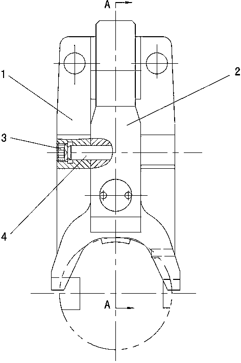
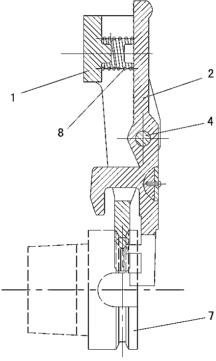
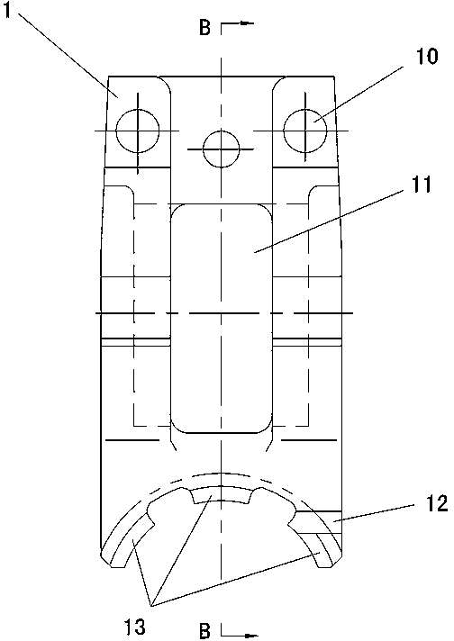
[0016] Such as figure 1 , 2 Shown: 1 is a fixed claw, 2 is a movable claw. The middle of the fixed claw 1 and the movable claw 2 are connected by a pin shaft 4. The specific connection method is that there are symmetrical fixed claw pin holes 14 on both sides of the middle of the fixed claw 1, and the movable claw 2 has a movable claw pin hole 26 in the middle, and the movable claw 2 Located in the middle, the pin shaft 4 is inserted in the fixed claw pin hole 14 and the movable claw pin hole 26, and the end is equipped with an axial limit screw 3 that is also screwed to the fixed claw 1 so that the movable claw 2 can be fixed relative to The pawl 1 rotates at a certain angle.

[0017] Such as image 3 , 4 , 5: There is a first spring support 15 at one end of the fixed claw 1. The other end of the fixed claw 1 is in the shape of an arc-shaped fork, and the inner side has a protrusion 13 that matches the groove on the outer circumference of the knife handle 7.

[0018] Such as Im...


PUM


Abstract

The invention provides a self-locking cutter quick exchange device which comprises a fixed claw and a movable claw. The middle of the fixed claw and the middle of the movable claw are in rotatable connection through a pin roll. A spring is arranged between one end of the fixed claw and one end of the movable claw, the other end of the fixed claw is of an arc-shaped fork shape, and a protrusion which is matched with a groove in the outer periphery of a cutter handle is arranged on the inner side of the other end of the fixed claw. The other end of the movable claw is provided with a hanging claw which is matched with a groove in the end face of the cutter handle and an anti-rotating boss which is matched with the an anti-rotating groove which is formed in the end face of the cutter handle, a collision head is arranged on the side face of the movable claw, and the collision head extends to the other side from a center hole in the fixed claw (1). According to the self-locking cutter quick exchange device, the cutter exchange time is short when a cutter is exchanged, the auxiliary time is shortened, the working efficiency is improved, the structure is simple due to few parts, the occupied space is small, and breakdowns can not happen easily.

Description

Technical field [0001] The invention relates to a tool changing device, in particular to a self-locking tool quick changing device used on machining equipment. Background technique [0002] At present, the automatic tool change device in the metal cutting machine tool consists of a tool clamping device and a tool change device. Compared with the cutting time, the tool change time is longer, the failure rate is high, and the space is large. Summary of the invention [0003] The purpose of the present invention is to provide a self-locking tool quick exchange device with few parts, simple structure, small space occupation, flexible and reliable action, and short tool change time, which overcomes the shortcomings of the prior art. [0004] The self-locking tool quick exchange device of the present invention includes a fixed claw and a movable claw. The middle of the fixed claw and the movable claw are connected by a pin shaft rotation; a spring is provided between one end of the fixed...

Claims


Application Information

Patent Timeline
Patent Type & Authority Applications(China)
IPC IPC(8): B23Q3/155
CPCB23Q3/15553B23Q3/157
Inventor 孙造邹运鞠修勇姜美娜唐倩李壮文怀栋刘航
Owner 通用技术集团大连机床有限责任公司
Why Eureka
Try Eureka