
Object absorbing device

An adsorption device and object technology, which is applied in the direction of conveyor objects, transportation and packaging, furnaces, etc., can solve the problems of unstable adsorption force, high energy consumption, and high surface flatness requirements, and achieve stable adsorption effect, large adsorption force, The effect of low energy consumption

Inactive Publication Date: 2014-01-08
ZHEJIANG UNIV
View PDF8 Cites 21 Cited by
  • Summary
  • Abstract
  • Description
  • Claims
  • Application Information

AI Technical Summary

Problems solved by technology

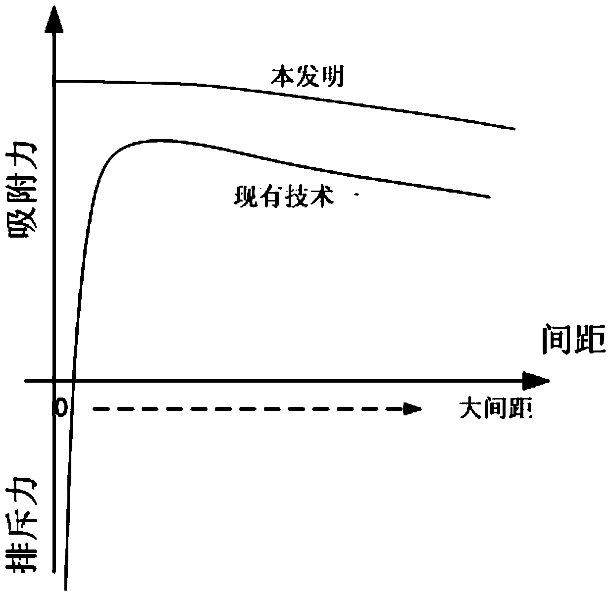
[0016] The present invention is an adsorption device that generates adsorption force, which can overcome the defects of the existing adsorption technology, such as high requirements on the flatness of the object surface, unstable adsorption force, small application range, and high energy consumption. Ability to generate and maintain a suction force even when there is a distance between the suction device and the object

Method used


Image

  • Object absorbing device
  • Object absorbing device
  • Object absorbing device

Examples


Embodiment Construction

[0034] Referring to the attached picture:

[0035] The object adsorption device includes a shell 1 with a circular cross section, and a cavity 11 with a circular cross section inside the shell. The cavity 11 has a closed end face and an open end face, and the open end face forms an adsorption end face. The motor 2 is installed on the closed end surface, and the fan blade 12 arranged in the cavity 11 is connected to the output shaft of the motor 2. The closed end surface is in an airtight state, and the fan blade 12 is arranged along the cavity of the cavity. The axes are distributed in a straight line, and the shell on the circumference of the opening end face may or may not contact the adsorbed object 3 during operation.

[0036] As mentioned above, the downdraft and crevice airflow of the prior art has an effect on the adsorption force. The present invention has no suction hole, and the fan blade has no bent part in the vertical direction, so it will not inhale air, nor wil...


PUM


Abstract

The invention discloses an object absorbing device. The object absorbing device comprises a shell with the cross section being circular, a cavity with the cross section being circular is formed in the shell, and the cavity is provided with a closed end face and an opened end face. The opened end face forms an end face for absorbing an object, the closed end face is provided with a motor, and fan blades arranged inside the cavity are connected with an output shaft of the motor. The object absorbing device is characterized in that the closed end face is in an airtight state, and the fan blades are in linear distribution along the axis of the cavity. In the working process, the shell on the circumference of the opened end face can apply absorption force on the object under the condition that the shell makes contact with or does not make contact with the object. The object absorbing device can be widely applied to absorbing and grasping objects, is suitable for the objects with large surface roughness and can also be adaptive to the object tilting condition, and the advantage of being small in energy consumption is achieved as well.

Description

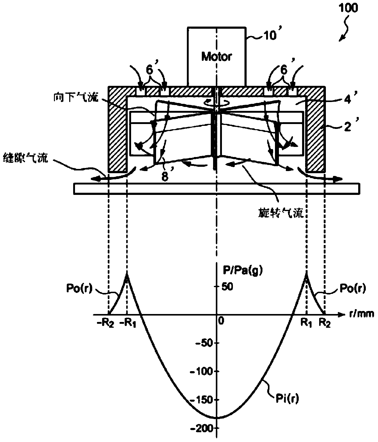
technical field [0001] The invention relates to a device for generating adsorption force. Background technique [0002] When carrying out adsorption and transportation of some precision components, such as semiconductor wafers, liquid crystal glass substrates, etc., we often use "non-contact adsorption devices" to carry out. [0003] Japanese patent JP2009-298331, hereinafter referred to as prior art one, its working principle is as follows figure 1 As shown, the mechanism drives the fan blades in the cylindrical housing to rotate the air through the motor, and the centrifugal force generated by the air rotation forms a certain degree of vacuum in the housing, thereby being able to absorb the smooth plate-shaped objects below. In addition, there are suction holes on the upper part of the mechanism casing, which are distributed around the motor; and the upper end of the fan blade has a small bent part, so when the fan blade rotates, a top-down airflow will be generated ( fi...

Claims


Application Information

Patent Timeline
Patent Type & Authority Applications(China)
IPC IPC(8): B65G47/91B65G49/06B65G49/07
Inventor 黎鑫
Owner ZHEJIANG UNIV
Learn More