
a filter valve

A filter valve and valve body technology, which is applied in the direction of filter separation, valve device, mechanical equipment, etc., can solve the problems of small filter area, filter deformation, waste of resources, etc., to improve the filter effect, increase the filter area, Wide range of effects

Inactive Publication Date: 2015-12-30
卓旦春
View PDF6 Cites 0 Cited by
  • Summary
  • Abstract
  • Description
  • Claims
  • Application Information

AI Technical Summary

Problems solved by technology

First of all, the filtering area of ​​the filter is small, and the size of each mesh on the filter is the same, so there is a requirement for the size of the impurities when filtering, and the impurity particles whose volume is larger than the mesh of the filter can be filtered, and the volume is smaller than that of the filter. The impurities in the mesh cannot be filtered, so the practical value is not high
In addition, when the flow rate of the medium is fast, the impurities will cause a greater impact on the surface of the filter screen, and because the filter screen is generally made of steel wire, the filter screen is prone to deformation after a long impact and loses the filtering effect, so the filter screen should be replaced frequently will cause waste of resources

Method used


Image

  • a filter valve
  • a filter valve
  • a filter valve

Examples


Embodiment 1

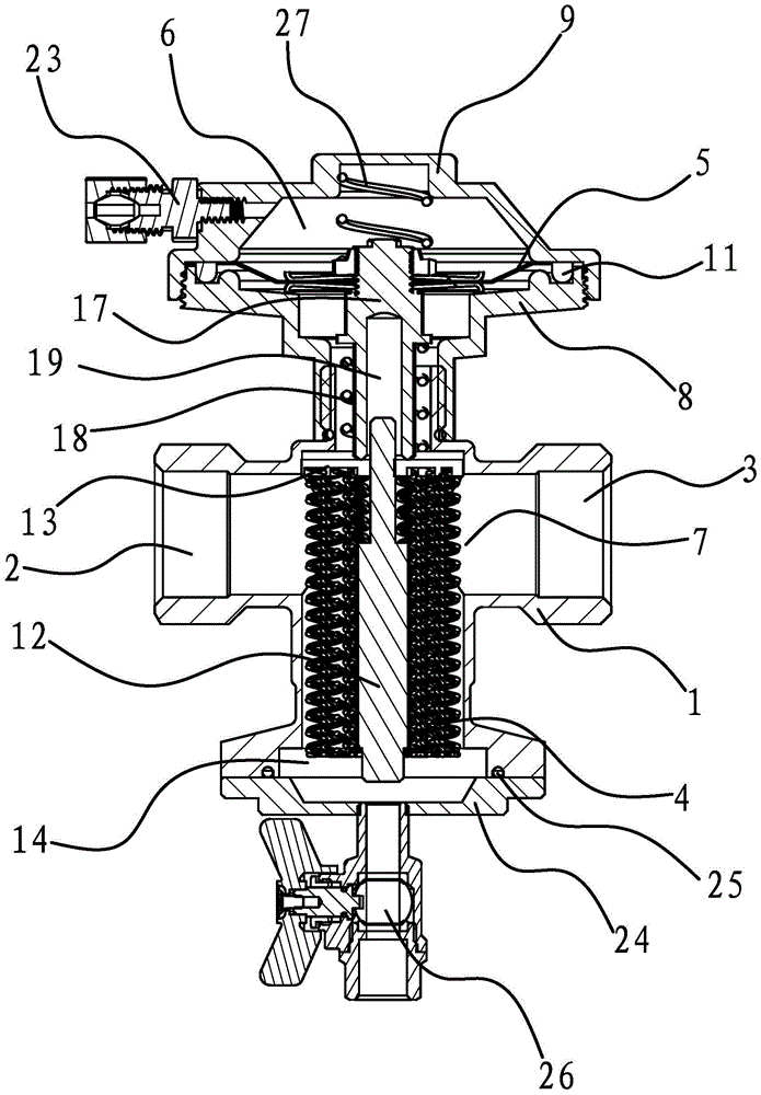
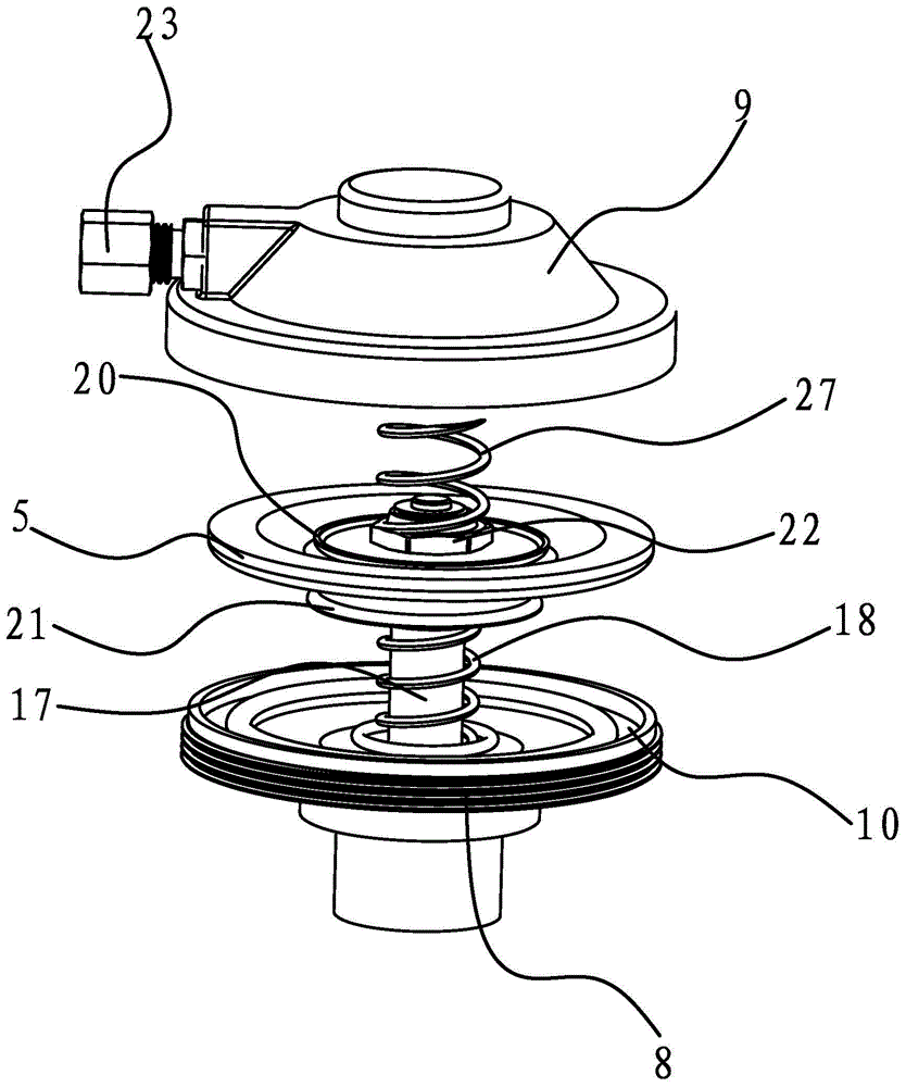
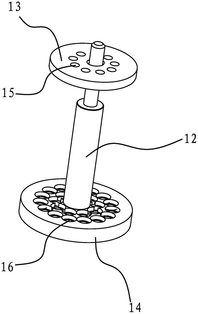
[0033] Such as figure 1 and image 3 As shown, a filter valve includes a valve body 1 with a cavity inside. The left and right ends of the valve body 1 are the water inlet 2 and the water outlet 3 respectively. A connecting rod perpendicular to the water flow direction is fixed in the valve body 1. 12. The upper end of the connecting rod 12 is covered with a baffle plate 13 and the lower end of the connecting rod 12 is fixed with a baffle plate 2 14. Several filter springs 4 are connected between the baffle plate 13 and the baffle plate 2 14, and the filter spring 4 The two ends lean against the first baffle plate 13 and the second baffle plate 14 respectively. The first baffle plate 13 and the second baffle plate 14 have a positioning hole 15 and a positioning hole 2 16 facing each other on the opposite surface respectively, and the two ends of the filter spring 4 are fixed in the positioning hole 1 15 and the positioning hole 2 16 respectively.

[0034] Such as figure 1 a...


PUM


Abstract

The invention provides a strainer valve, and belongs to the technical field of machines. The strainer valve solves the problems that an existing strainer valve cannot filter off impurities completely and a filter screen is broken easily. The strainer valve comprises a valve body, wherein a cavity is formed inside the valve body; the left end and the right end of the valve body are a water inlet end and a water outlet end respectively; a filtration spring which is perpendicular to the waterflow direction and a membrane located above the filtration spring are fixed in the valve body; a stressed part is fixed at the bottom of the membrane; the two ends of the filtration spring abut against the inner wall of the stressed part and the inner wall of the valve body respectively; the membrane partitions the valve body off into a control cavity and a filtration cavity, wherein the filtration cavity is communicated with the water inlet end and the water outlet end of the valve body; a pressure guide connecting pipe communicated with the control cavity is further connected to the side portion at the upper end of the valve body. The strainer valve has the advantages that the filtration effect is good and the filtration function is not affected by changes in hydraulic pressure.

Description

technical field [0001] The invention belongs to the technical field of machinery and relates to a filter valve. Background technique [0002] Filter valve, also known as filter, is a device for filtering pretreatment and an indispensable device for the pipeline series of conveying media. It is usually installed at the inlet end of water conservancy control valves, pressure reducing valves, constant water level valves and other equipment , used to eliminate impurities in the medium, prevent granular impurities from entering the channel, and protect the fittings on the equipment pipeline from wear and blockage. [0003] Filter valves are widely used in industrial production and daily life. At present, the most commonly used filter valve is a filter valve with a filter screen inside, that is, a layer of filter screen is set in the valve body of the filter valve to filter impurities. For example, a Chinese patent discloses a filter valve [Application No.: 201020300385.0; Announ...

Claims


Application Information

Patent Timeline
Patent Type & Authority Patents(China)
IPC IPC(8): F16K51/00B01D35/04
CPCB01D35/04F16K51/00
Inventor 卓旦春
Owner 卓旦春
Learn More