Flexural rigidity testing device in copious cooling and high-temperature environments

A high-temperature environment, bending stiffness technology, applied in the direction of testing the strength of materials by applying a stable bending force, can solve the problem that the laser emitter cannot be located on the component and follow the three-dimensional displacement of a certain point, and achieve accurate measurement of the deflection angle Deformation, good real-time performance, and high measurement accuracy

Active Publication Date: 2014-01-08
求法问律(菏泽)法律咨询服务有限公司
View PDF5 Cites 11 Cited by
  • Summary
  • Abstract
  • Description
  • Claims
  • Application Information

AI Technical Summary

Problems solved by technology

However, for the stiffness test at high and low temperatures, the laser emitter cannot be located on the component, and the deformation of the machine base must also be taken into account during the test
The patent application number is 201110370253.4 for "three-dimensional deformation measurement device of the tested part in the high and low temperature box" and the patent application number is 201110370271.2 for the "high precision measurement system for three-dimensional small deformation of the mechanical device in the high and low temperature box" to provide a high and low temperature box The measurement method of three-dimensional deformation of components, but this kind of method can only follow the three-dimensional displacement of a certain point, and the stiffness test needs to obtain accurate loading force and the size of the moment arm

Method used


Image

  • Flexural rigidity testing device in copious cooling and high-temperature environments
  • Flexural rigidity testing device in copious cooling and high-temperature environments

Examples


Embodiment Construction

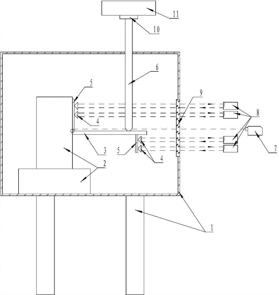
[0026] combine Figure 1 to Figure 2 , Bending stiffness testing device under cryogenic and high temperature environment, including laser displacement sensor 7, high stiffness rod 6, corner mirror 4, laser measurement group, force sensor 10, lifting device 11 and so on.

[0027] The DUT 3 and its mounting base 2 are placed in a high and low temperature box, one end of the high rigidity rod 6 is fixedly connected to the lifting device 11, and the other end of the high rigidity rod 6 is a smooth spherical surface and vertical Directly acting on the tested object 3, a force sensor 10 is installed between the high rigidity rod 6 and the lifting device 11.

[0028] The laser displacement sensor 7 is installed outside the high and low temperature box 1, the measurement direction of the laser displacement sensor 7 is parallel to the direction of the force arm, and the measurement point of the laser displacement sensor 7 is close to the DUT 3 and the DUT mounting seat 2 the roots.

...


PUM


Abstract

The invention discloses a flexural rigidity testing device in copious cooling and high-temperature environments. The flexural rigidity testing device comprises a laser displacement sensor, a high-rigidity rod, a laser measurement group, a force sensor, a lifting device and a high-low temperature chamber, wherein a to-be-tested member is fixed in the high-low temperature chamber through a to-be-tested member installing base, the high-rigidity rod vertically penetrates through the high-low temperature chamber to act on the to-be-tested member, the upper end of the high-rigidity rod is fixedly connected with the lifting device through the force sensor, and the laser displacement sensor and the laser measurement group are arranged outside the high-low temperature chamber and are opposite to an observation window. According to the flexural rigidity testing device, loading is carried out by the high-rigidity rod, the direction of an acting force is not changed, a measurement moment arm is obtained by the laser displacement sensor, corner deformation is obtained by the laser measurement group, and thus a bending moment-angular deformation curve of the flexural rigidity of the to-be-tested member is accurately obtained. The flexural rigidity testing device is convenient to use, high in reliability, good in instantaneity and high in measurement precision.

Description

technical field [0001] The invention relates to the field of bending stiffness testing of components under cryogenic and high temperature environment conditions. Background technique [0002] Stiffness tests on structural parts are usually carried out at room temperature unless there are special requirements. Existing stiffness tests have many methods and structures according to different test requirements and application fields, but for components in high and low temperature environments Stiffness test, due to thermal expansion and contraction of test fixtures, loading mechanisms, etc. in high and low temperature environments will cause deformation, which will affect the loading of force, measurement of torque and angle, and because of the overheating and cooling of the environment, most of the tests use precision Instruments or equipment will not work normally, affecting the testing work. [0003] At present, the bending stiffness test under high and low temperature is ca...

Claims


Application Information

Patent Timeline
Patent Type & Authority Applications(China)
IPC IPC(8): G01N3/20
Inventor 孙建辉周丹锋
Owner 求法问律(菏泽)法律咨询服务有限公司
Why Eureka
Try Eureka