Drawer

A drawer and connector technology, which is applied to drawers, furniture parts, household appliances, etc., can solve the problems of inability to adjust and replace, insufficient supporting capacity, effective accommodation space, etc., and achieves beautiful and practical applicability, low production cost, Quick and easy disassembly

Active Publication Date: 2014-01-15
伍志勇
View PDF9 Cites 18 Cited by
  • Summary
  • Abstract
  • Description
  • Claims
  • Application Information

AI Technical Summary

Problems solved by technology

It is said that this invention has the advantages of simple structure, durability and reliability compared with the existing drawers. However, once the new drawer of this structure is formed, it cannot be adjusted and replaced, and it can only be applie

Method used


Image

  • Drawer
  • Drawer
  • Drawer

Examples


Example

[0032] first embodiment

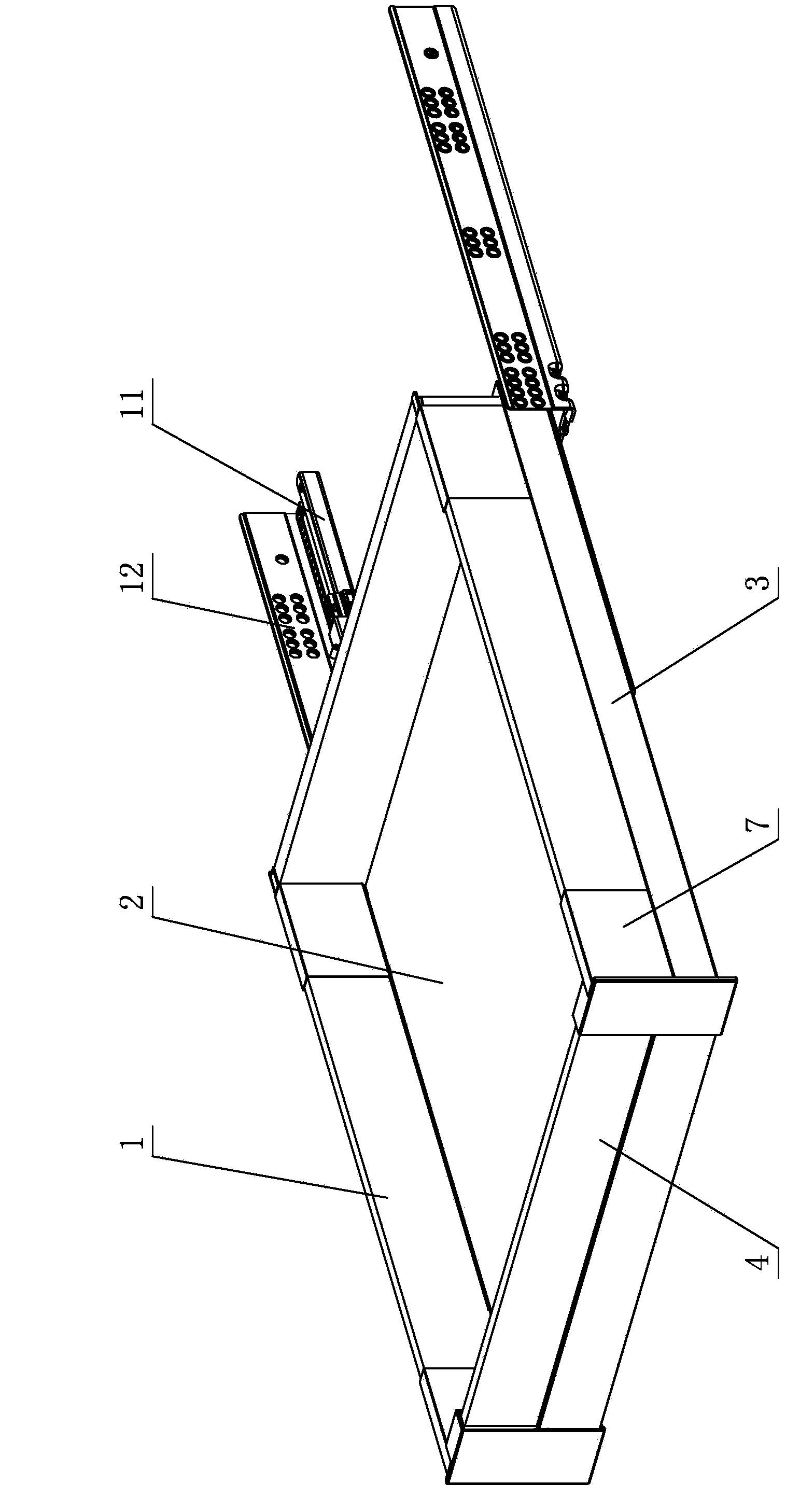
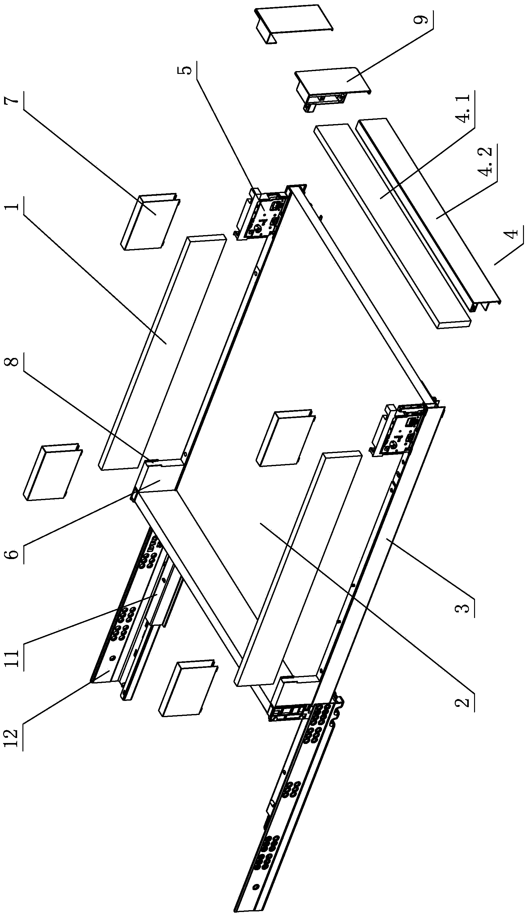
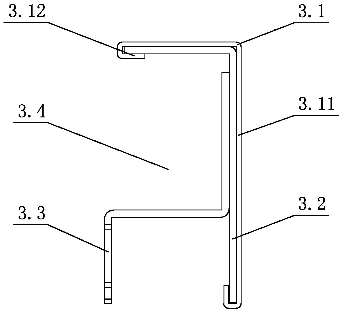
[0033] see figure 1 - Figure 22 , a drawer, comprising a side plate 1, a bottom plate 2, a support rail 3 and a slide rail assembly for opening and closing the drawer, the support rail 3 is integrally formed by metal or at least two pieces of metal profiles are separately arranged and then fixed into one, supporting The upper side of the rail 3 is bent downward, and a front connector 5 connected to the front panel 4 and a rear connector 6 connected to the back panel are arranged on it; the side panel 1 is arranged on the upper part of the support rail 3 and placed Between the front connector 5 and the rear connector 6; the front connector 5 and / or the rear connector 6 is provided with a decorative cover 7 made of metal; the bottom plate 2 is arranged on the support rail 3; the front panel 4 or the connector seat 9 It abuts against the front connecting piece 5 and the support rail 3 .

[0034] Specifically, the support rail 3 is formed by at least ...

Example

[0052] Second Embodiment

[0053] see Figure 23 , Figure 24 , This drawer is different from the first example in that: the front panel 4 is made of glass, metal, plastic, stone or wood, and is connected with the front connecting piece 5 through the front connecting block 10. The front connector 5 is provided with a positioning table 5.2 corresponding to the front panel 4, and the back of the front panel 4 abuts against the support rail 3 and the positioning table 5.2;

[0054] Alternatively, the front connecting piece 5 is provided with a positioning block 5.3 corresponding to the front connecting block 10, the two abut against each other, and the back of the front panel 4 also abuts against the support rail 3.

[0055] Other unmentioned parts are the same as those of the first embodiment.


PUM


Abstract

The invention relates to a drawer which comprises lateral plates, a base plate, a supporting rail and a sliding rail assembly for opening and closing a drawer body. The supporting rail is integrally molded through metal or formed in the mode that at least two metal sections are arranged in a split mode and then fixedly combined into a whole, one side of the upper portion of the supporting rail is downwards bent, and a front connecting piece connected with a front panel and a rear connecting piece connected with a rear back plate are arranged on the side of the upper portion of the supporting rail. The lateral plates are arranged on the upper portion of the supporting rail and arranged between the front connecting piece and the rear connecting piece. A decoration cover is arranged on the front connecting piece and/or the rear connecting piece. The base plate is arranged on the supporting rail. The front panel or a connecting base abuts against the front connecting piece and the supporting rail. By means of an improvement on the structure, selected materials of the lateral plates, the front panel, the rear back plate and the base plate are not influenced by drawer assembly components, the drawer can be tailored according to requirements of users, the drawer of the structure is high in market competitiveness, and is suitable for consumers, attractive and practical.

Description

technical field [0001] The invention relates to a drawer. Background technique [0002] The Chinese patent literature number is CN201008445, which discloses a novel drawer on January 23, 2008. It includes a front panel, a rear panel, side panels on both sides and a bottom panel. end, the bottom plate is glued to the bottom end of the side plate, the width of the bottom plate is greater than the distance between the side plates on both sides, thus forming a flange that can sink into the guide rail of the vertical plate of the locker, because the width of the bottom plate is greater than two The distance between the side panels on the side, thereby forming a flange that can sink into the guide rail of the locker vertical plate, and the flange slides in the guide rail to realize the opening and closing of the drawer. It is said that this invention has the advantages of simple structure, durability and reliability compared with the existing drawers. However, once the new drawer...

Claims


Application Information

Patent Timeline
IPC IPC(8): A47B88/08A47B88/00A47B88/49
Inventor 伍志勇
Owner 伍志勇
Why Eureka
Try Eureka