
Multi-electrode type all-directional luminous LED light source and bracket thereof

An LED light source, all-round technology, applied in the direction of light source, light source combination, light source fixation, etc., can solve the problem of treating symptoms but not the root cause, no LED all-round light, limited illuminated area, etc., to achieve strong market competitiveness and lighting orientation. Wide and easy to install

Pending Publication Date: 2018-03-30
DONGGUAN LIGHT SOURCE OPTO TECH
View PDF0 Cites 6 Cited by
  • Summary
  • Abstract
  • Description
  • Claims
  • Application Information

AI Technical Summary

Problems solved by technology

However, LED lights also have certain defects: due to the strong directionality of the light emitted by the LED chip, its illuminated area is limited, unlike incandescent lamps and energy-saving lamps where the light source is divergent.
The disadvantages of this method are obvious: the cost is high, and the assembly process is complicated due to the need to install multiple LEDs on the lamp head
It can be seen that this solution is only to treat the symptoms but not the root cause, and does not solve the problem of LED lighting in all directions from the source.
[0010] In addition, the multiple LEDs installed in the light-emitting lamp head of the lamp are all connected in series. When they are working, they are all lit or extinguished at the same time. LEDs of different colors are more difficult to adjust the light, causing greater trouble to users
Although there are some LEDs installed on the PCB board to controllably adjust the light emission, they can only achieve planar light emission and cannot achieve the purpose of omnidirectional light emission.

Method used


Image

  • Multi-electrode type all-directional luminous LED light source and bracket thereof
  • Multi-electrode type all-directional luminous LED light source and bracket thereof
  • Multi-electrode type all-directional luminous LED light source and bracket thereof

Examples


Embodiment Construction

[0030] The present invention will be further described below in conjunction with specific embodiments and accompanying drawings.

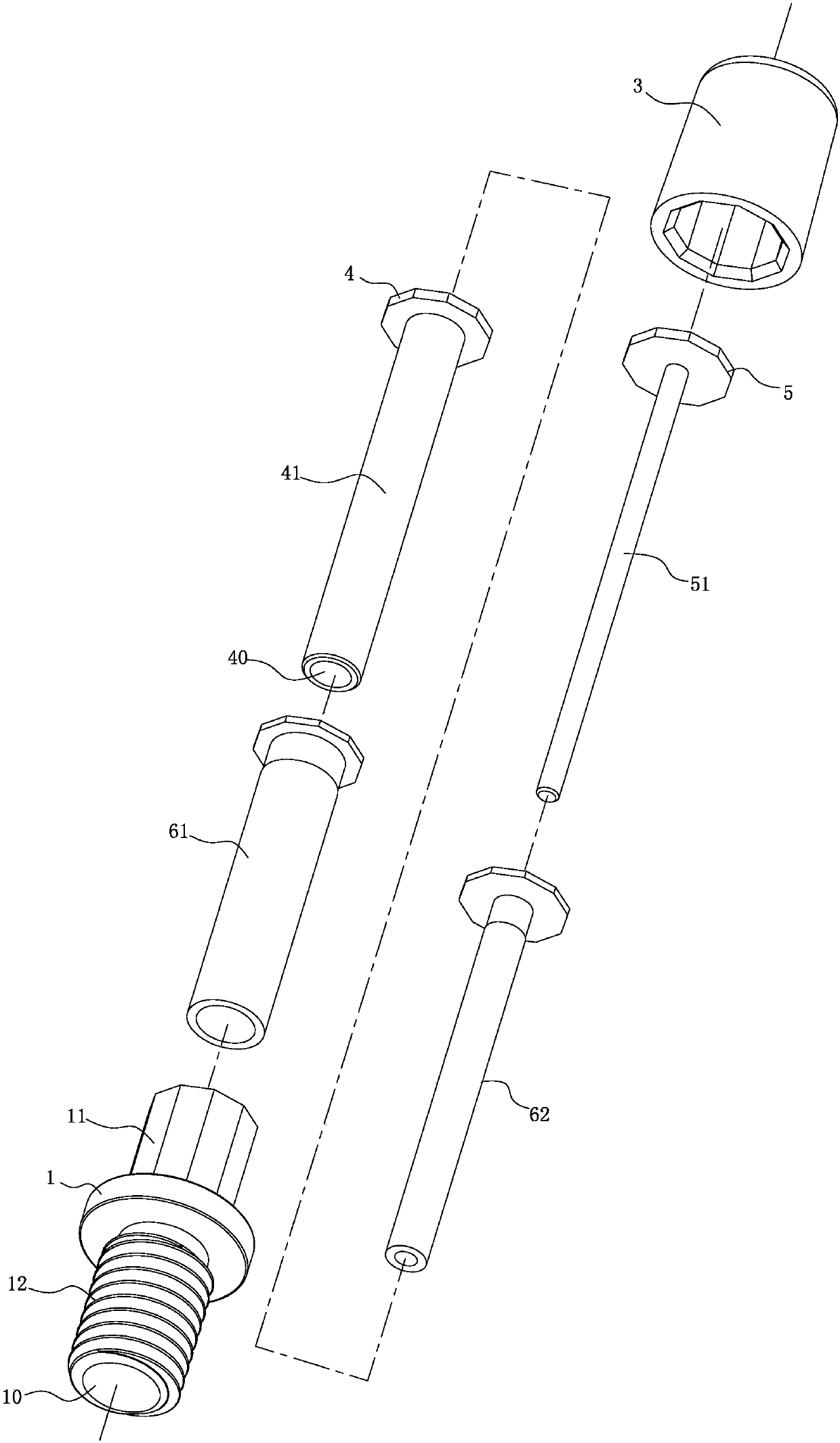
[0031] See Figure 1-6 As shown, it is a multi-pole omni-directional LED light source, which includes: a bracket 1, a number of LED chips 2 mounted on the bracket 1, and a resin 3 for packaging the LED chips 2 on the bracket 1, the bracket 1 is provided with a multi-level packaging pole structure 100 that is insulated from each other and used to conduct LED chips 2. The LED chip 2 is installed around and on the top of the multi-level packaging pole structure 100, so that the present invention can realize omnidirectional light emission. . The present invention can be widely used in various lighting fixtures. Compared with the current LED lighting fixtures, it has the advantages of small size, wide lighting orientation and convenient installation.

[0032] The plurality of LED chips 2 include at least two LED chips 2 of different colors to meet dif...


PUM


Abstract

The invention discloses a multi-electrode type all-directional luminous LED light source and a bracket thereof. The multi-electrode type all-directional luminous LED light source comprises the bracket, a plurality of LED chips installed on the bracket, and resin; the bracket is provided with a multi-stage packaging electrode table structure which is insulated and used for being in conductive connection with the LED chips; the LED chips are installed on the periphery and top of the multi-stage packaging electrode table structure; the multi-stage packaging electrode table structure comprises a first-stage packaging electrode table formed at the upper end of the bracket, a second-stage packaging electrode table and a third-stage packaging electrode table, wherein the second-stage packaging electrode table and the third-stage packaging electrode table are stacked on the first-stage packaging electrode table in sequence, and the first-stage packaging electrode table, the second-stage packaging electrode table and the third-stage packaging electrode table serve as a first conductive electrode, a second conductive electrode and a third conductive electrode correspondingly and are insulated from one another; and a first electrode and a second electrode of each LED chip are in conductive connection with the first-stage packaging electrode table and the second-stage packaging electrode table, or in conductive connection with the first-stage packaging electrode table and the third-stage packaging electrode table, or in conductive connection with the second-stage packaging electrode table and the third-stage packaging electrode table.

Description

Technical field: [0001] The invention relates to the technical field of LED products, in particular to a multi-pole omnidirectional LED light source and a bracket thereof. Background technique: [0002] As we all know, traditional incandescent lamps have high energy consumption and very low energy utilization rate. Only less than one tenth of the energy is converted into light energy, and the rest is wasted as heat energy. So people have been trying to find ways to replace incandescent lamps with new light sources. Therefore, energy-saving lamps came into being. Because it is cheaper and easier to manufacture than incandescent lamps, it has been widely used and has a tendency to gradually replace incandescent lamps. Energy-saving lamps use the principle of electronic excitation to emit light. Compared with incandescent lamps, energy-saving lamps have the advantage of saving electricity. But one disadvantage of energy-saving lamps is that energy-saving lamps contain mercur...

Claims


Application Information

Patent Timeline
IPC IPC(8): F21K9/20F21V17/10F21V19/00F21V23/04F21V23/06H01L25/075H01L33/48F21Y113/17F21Y115/10
CPCH01L25/0753H01L33/483F21K9/20F21V17/101F21V19/002F21V23/04F21V23/06F21Y2115/10F21Y2113/17
Inventor 王进
Owner DONGGUAN LIGHT SOURCE OPTO TECH
Learn More