
Shot derusting machine for inner wall of super-long pipeline

A rust removal machine and pipeline technology, which is applied in abrasive jet machine tools, used abrasive treatment devices, abrasive materials, etc., can solve the problems affecting workers' health and safety, high economic cost of comprehensive rust removal, and high labor intensity for workers. , to achieve the effect of saving dust removal equipment, saving production preparation time, and saving the link of recycling steel grit

Active Publication Date: 2014-01-15
张 国祯
View PDF6 Cites 1 Cited by
  • Summary
  • Abstract
  • Description
  • Claims
  • Application Information

AI Technical Summary

Problems solved by technology

[0002] At present, on the pipeline anti-corrosion engineering site, the rust removal of the inner wall of the batch standard pipe length steel pipe is basically carried out by means of a production line. , or the inner wall derusting of super-standard pipe length steel pipes. For the situation of many types of pipe diameters and small number of steel pipes, in order to reduce the operating cost of the production line, artificial shot peening is often used to derust the inner wall of steel pipes. The method causes the labor intensity of the workers to be high, affects the health and safety of the workers, the production efficiency is low, wastes energy, pollutes the environment, occupies a large workplace, and the economic cost of comprehensive derusting is high; As far as the current production line is concerned, it is difficult to satisfy the rust removal on the inner wall of steel pipes over 13 meters long. If the production line is modified, it will cost a lot of money and occupy a lot of space

Method used


Image

  • Shot derusting machine for inner wall of super-long pipeline

Examples


Embodiment Construction

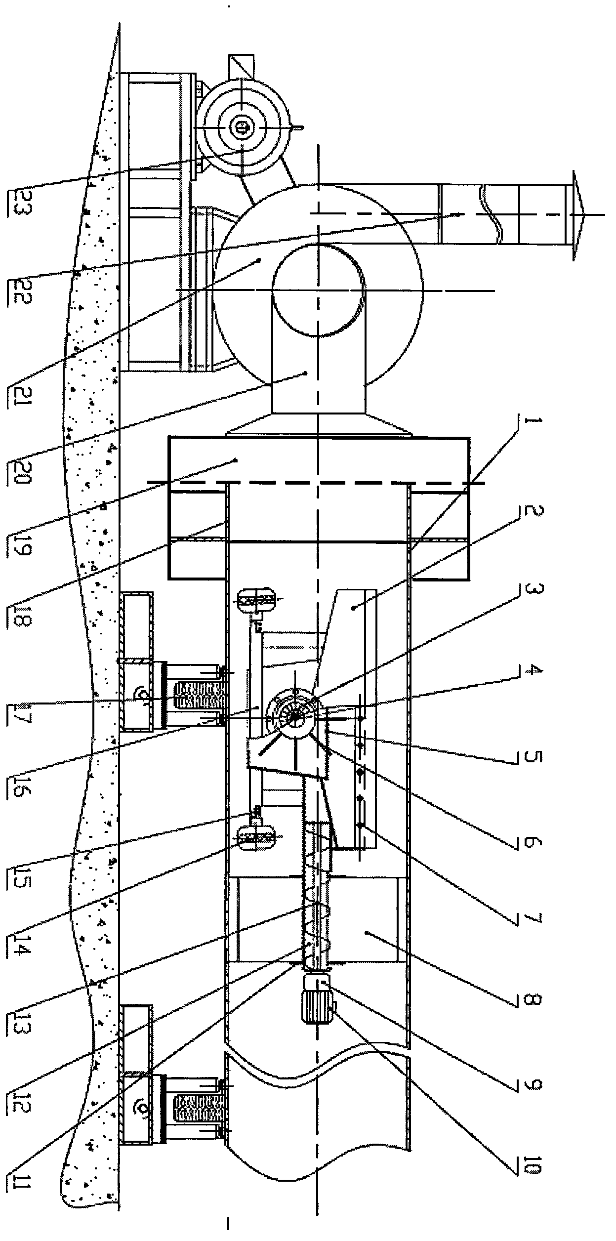
[0017] see figure 1 :

[0018] The steel pipe 1 to be derusted is placed on the rotating power bracket 17 of the steel pipe, and one end of the steel pipe 1 to be derusted is placed in the trolley transition cabin 18, dust collection box and dust filter device 19, and the trolley transition cabin 18 is connected with the dust collection box and dust filter. The filtering device 19 is connected to the air induction pipe 20, the dust removal induced draft fan 21, and the exhaust air duct 22 in sequence. Driven by the fan power motor 23, the dust removal work can be carried out; the sand storage box 2 is connected with the steel sand recovery wing device 12 , in this recovery wing device 12, be provided with steel sand collecting auger conveying mechanism 13; Derusting machine main frame 16 is provided with derusting machine walking wheel 14, and angle adjustable walking wheel support frame 15, in derusting machine main The sand storage box 2 is installed on the frame 16; the ro...


PUM


Abstract

The invention relates to a shot derusting machine for the inner wall of a super-long pipeline. The shot derusting machine comprises a sand storage box body, a sand conveying hopper of a blast wheel power motor, a sand conveying box body, a rotary blast wheel with an impeller, a steel sand collecting wing in a pipeline, a power motor of a sand return device, a supporting device of the steel sand collecting wing, a recovery device of the steel sand collecting wing, a conveying mechanism of a steel sand collecting auger, a travelling wheel of the derusting machine, an angle-adjustable travelling wheel supporting frame, a dedusting induced draft fan, and a power motor of a fan. The derusting machine is provided with the angle-adjustable travelling wheel and can linearly travel in the steel pipeline through rotation of the steel pipeline. Derusting operation to the inner wall of the steel pipeline can be carried out by controlling the sand storage box and an automatic sand amount adjusting valve. The steel sand automatic recovery device at the rear end of the derusting machine can collect steel sand in the pipeline and return the steel sand to the sand storage box so as to realize the purpose of recycling the steel sand. Under the equal pipeline wall derusting condition, efficient, energy-saving and clean effects can be realized in the derusting work of the inner wall of the pipeline.

Description

Technical field: [0001] The invention relates to a shot blasting rust removal machine for the inner wall of a pipeline, mainly an ultra-long pipeline inner wall shot blasting rust removal machine, which belongs to the field of metal processing rust removal. Background technique: [0002] At present, on the pipeline anti-corrosion engineering site, the rust removal of the inner wall of the batch standard pipe length steel pipe is basically carried out in the form of a production line. , or the inner wall derusting of super-standard pipe length steel pipes. For the situation where there are many types of pipe diameters and a small number of steel pipes, in order to reduce the operating cost of the production line, artificial shot peening is often used to derust the inner wall of steel pipes. The method causes high labor intensity of workers, affects workers' health and safety, low production efficiency, waste of energy, pollutes the environment, occupies a large workplace, and...

Claims


Application Information

Patent Timeline
Patent Type & Authority Applications(China)
IPC IPC(8): B24C3/02B24C3/16B24C9/00
Inventor 张景远张国祯李军阳涛丁振铭王国荣
Owner 张 国祯
Learn More