
Molding device and operating method thereof

A technology of a molding device and an operation method, which is applied to other household appliances, optical components, household appliances, etc., can solve the problems of low alignment accuracy, difficult correction, center deviation, etc., to increase product production efficiency, and increase the ease of manufacturing and assembly. , Improve the effect of machining accuracy

Inactive Publication Date: 2014-01-15
SAMSUNG ELECTRO MECHANICS CO LTD
View PDF5 Cites 0 Cited by
  • Summary
  • Abstract
  • Description
  • Claims
  • Application Information

AI Technical Summary

Problems solved by technology

[0003] However, conventionally, when the fixed-side mold and the movable-side mold used for molding optical devices etc. are combined, the alignment accuracy is low
In particular, even in the case of using the method of the prior art document, since the tapered concave portion and the tapered convex portion need to be processed separately, the assembly processing technology is required to have high alignment accuracy, and since the upper and lower parts There is a gap between the fixed side product core and the movable side product core related to the fixed side molding surface and the movable side molding surface, and the decenter (decenter) that causes the center deviation between the upper and lower cavities is difficult to carry out. fix

Method used


Image

  • Molding device and operating method thereof
  • Molding device and operating method thereof
  • Molding device and operating method thereof

Examples


Embodiment Construction

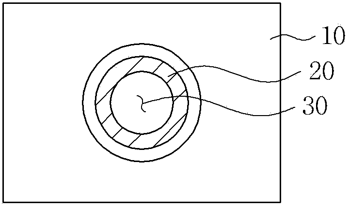
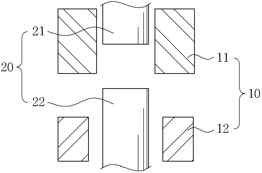
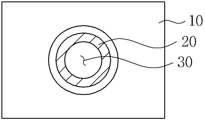
[0042]The purpose, specific advantages, and innovative features of the present invention will become more apparent from the following detailed description and preferred embodiments associated with the accompanying drawings. In this specification, when referring to the components of each drawing, the reference symbols are limited to the same components, and even if they are shown in different drawings, the same symbols are used as much as possible. In addition, terms such as "one side", "the other side", "first", and "second" are used to distinguish one constituent element from other constituent elements, and the constituent elements themselves are not limited by the terms. In particular, the upper and lower directions of the present invention are Figure 2b Based on the drawing shown in , the part forming the upper core and upper formwork on one side is called "upper part", and the part on the other side forming the lower core and lower formwork plate is called "lower part". ...


PUM


Abstract

The invention relates to a molding device and an operating method thereof. A side face is formed in the direction of one side of an upper part or a lower part of an assembling line of an upper part template and a lower part template, and the side face is formed inside the upper part template and the lower part template and used for an assembling line part of an upper part mold core and a lower part mold core that form cavities, thereby enabling the cavities of the upper part mold core and the lower part mold core to be combined and integrally arranged on the side face of an inner side of the upper part template or the lower part template.

Description

technical field [0001] The present invention relates to forming apparatus and methods of operation thereof. Background technique [0002] In general, for optical devices made of resin materials such as lenses, the fixed side mold and the movable side mold are formed on the upper and lower parts respectively, and the molding surfaces are aligned and combined to form a cavity between the two. Molten resin is injected into the cavity for molding. In order to align the arrangement of the optical components, a cylindrical guide sleeve is generally provided on the fixed side mold for injecting a guide pin protruding from the lower surface of the movable side mold to align the fixed side. The arrangement that the mold and the movable side mold are combined at the upper and lower parts. For example, as described in Japanese Laid-Open Publication No. 2009-120097, the bottom surface of the tapered groove and the tapered convex part are respectively formed for the injection combinati...

Claims


Application Information

Patent Timeline
Patent Type & Authority Applications(China)
IPC IPC(8): B29C45/26B29C45/27B29L11/00
CPCB29C45/2606B29C45/27B29L2011/0016B29C33/005B29C45/2701B29C45/2708B29C45/36
Inventor 朴胜洙崔良洙全泳鲁
Owner SAMSUNG ELECTRO MECHANICS CO LTD
Learn More