Flow stabilizing tank

A technology of stabilizing tanks and tanks, which is applied in the field of constant pressure stabilizing tanks, and can solve the problems that the pressure cannot be kept constant.

Inactive Publication Date: 2014-01-15
SHANGHAI LIANCHENG(GRP) CO LTD
View PDF5 Cites 8 Cited by
  • Summary
  • Abstract
  • Description
  • Claims
  • Application Information

AI Technical Summary

Problems solved by technology

[0003] The purpose of the invention is to overcome the problem that the pressure cannot be kept constant in the prior art, and propose a new type of steady flow tank

Method used


Image

  • Flow stabilizing tank

Examples


Embodiment Construction

[0009] The present invention will be described in detail below in conjunction with the drawings and embodiments.

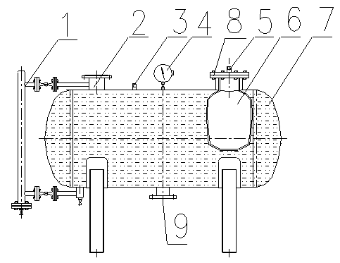
[0010] figure 1 Shown is a steady flow tank, including: a tank body 7, the tank body 7 is provided with a water inlet through which a water supply source flows into the tank body 2, a water outlet through which the water supply source flows out of the tank body, and is used to detect the water level in the tank body The high and low level gauge 1, the pressure gauge 4 for detecting the pressure in the tank and the exhaust valve 3 for the gas in the tank to discharge outward, characterized in that: the tank 7 is provided with an elastically deformable energy storage Airbag 6.

[0011] The energy storage airbag 6 includes a bag body located inside the tank body, which is filled with gas; the top of the bag body is fixed on the air bag opening 8 provided on the tank body, and an inflation valve 5 (inflatable Turn on the inflation at the time, and turn off after the char...


PUM


Abstract

The invention discloses a flow stabilizing tank. The flow stabilizing tank comprises a tank body, the tank body is provided with a water inlet, a water outlet, a liquidometer, a pressure gauge and an exhaust valve, wherein a water source enters the tank body through the water inlet, the water source flows out of the tank body through the water outlet, the liquidometer is used for detecting the water level in the tank body, the pressure gauge is used for detecting the pressure in the tank body, and the gas in the tank body is exhausted through the exhaust valve. The flow stabilizing tank is characterized in that an energy storage gas bag capable of being elastically deformed is arranged inside the tank body. The flow stabilizing tank has the advantages that maintaining is easy and convenient, exhausting is complete, no air exists in the tank body, the sanitation and hygiene of water quality are guaranteed, more importantly, the flow stabilizing tank can prevent the negative pressure from being produced, the pressure difference brought by pressure drop when a municipal pipe is in a busy hour can be automatically compensated, and the overlying time can be long and stable.

Description

Technical field [0001] The invention relates to a non-negative pressure water supply equipment, in particular to a constant pressure stable flow tank, which is integrated with a municipal pipe network to eliminate negative pressure, eliminate secondary pollution, and intelligently compensate for water flow. Background technique [0002] With the formulation and implementation of national energy-saving and emission reduction targets, people's requirements for the quality of drinking water are getting higher and higher. The clean, hygienic and safe water quality has become a strong demand from users. The old steady flow tank can only play a role in stabilizing the flow. When the pressure of the municipal pipe network drops, it cannot maintain a constant pressure, that is, a pressure difference is formed, which affects the normal operation of the municipal pipe network equipment. In view of the above situation, a new type of steady flow device is urgently needed to solve the above ...

Claims


Application Information

Patent Timeline
Patent Type & Authority Applications(China)
IPC IPC(8): E03B11/00
Inventor 逯海堂张锡淼
Owner SHANGHAI LIANCHENG(GRP) CO LTD
Why Eureka
Try Eureka