A device that converts circular rotation into linear reciprocating motion

A linear reciprocating motion and conversion technology, applied in the direction of transmission, belt/chain/gear, mechanical equipment, etc., can solve the problem that the relative frequency cannot be accelerated, achieve small lateral component force, reduce wear and heat, power waste less effect

Active Publication Date: 2015-10-28
南通智博电子线缆有限公司
View PDF5 Cites 0 Cited by
  • Summary
  • Abstract
  • Description
  • Claims
  • Application Information

AI Technical Summary

Problems solved by technology

[0004] The technical problem to be solved in the present invention is to overcome the defect that the relative frequency of the slider driven by the connecting rod cannot be accelerated in the crank-link mechanism of the prior art, and provide a swing reciprocating transmission device in which the connecting rod can increase the frequency. Unit also reduces power waste, reduces wear and heat

Method used


Image

  • A device that converts circular rotation into linear reciprocating motion
  • A device that converts circular rotation into linear reciprocating motion
  • A device that converts circular rotation into linear reciprocating motion

Examples


Embodiment 1

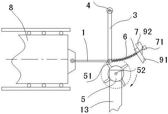
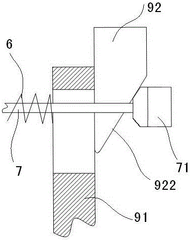
[0024] Embodiment 1: as figure 1 As shown, a device that converts circular rotation into linear reciprocating motion includes a connecting rod 1 whose back head is pinned to the slider. Rotationally connected, the upper end of the swing link 3 is rotatably connected with the pin rod 4 fixed on the machine base 13, and a 4-tooth dial 5 is arranged at the lower part of the front end of the connecting rod 1, and the dial teeth of the dial 5 51 and the pin shaft 2 can be pressed intermittently, the dial 5 is fixedly connected to the rotating shaft 52 connected to the machine base through bearings, and the rotating shaft 52 is connected to a transmission mechanism; the lower end of the swing rod 3 is pressed against one end of a compression spring 6 , The other end of compression spring 6 bears on the spring seat that is located on the clutch. The face of the shifting tooth 51 of the dial 5 facing the pin shaft 2 is a plane passing through the axis of the rotating shaft 52, and th...

Embodiment 2

[0029] Embodiment 2: The compression spring 6 of Embodiment 1 is removed, and the upper end of the swing rod 3 is fixedly connected with the weight rod 61. The weight rod 61 forms an angle of 70-90° with the swing rod 3 and forms a cantilever structure. The weight The tail end of the rod 61 is fixedly connected to the weight 62, the effect of the weight 62 on the swing rod 3 is equivalent to that of the compression spring 6 on the swing rod 3, see the attached Figure 6 .

[0030] The present invention is especially suitable for converting magnetic energy into mechanical rotation power. The magnetic energy power machine is a machine that uses a very small force to stimulate the release of magnetic energy and drive the power machine to run. The transmission process is: external force—magnetic power—mechanical energy; This device is through the process of external force - the conversion mechanism of this device - magnetic energy power - generator, that is, the circular rotation ...


PUM


Abstract

The invention discloses a device converting circular rotation to linear reciprocating motion. The device overcomes the defect in the prior art that the relative frequency of the motion of a sliding block driven by a connection rod of a crank connection rod mechanism can not be accelerated. The device comprises a connection rod, wherein the rear end of the connection rod is in pin joint connection with a dragging piece and the front end of the connection rod is rotably connected with the lower end portion of a swing rod through a pin shaft, and the swing rod is arranged above the connection rod. The upper end portion of the swing rod is rotably connected with a pin rod fixed to a base; a stirring wheel with at least two teeth is arranged below the front end of the connection rod; the stirring teeth of the stirring wheel abut against the pin shaft in an interval mode; the stirring wheel is fixedly connected with a rotating shaft, and the rotating shaft is connected to the base through a bearing; the rotating shaft is connected with a transmission mechanism; the lower end portion of the swing rod abuts against one end of a compression spring, and the other end of the compression spring abuts against a spring seat arranged on a clutch. The device converting circular rotation to linear reciprocating motion is used for frequency-increasing swing reciprocating transmission devices and has the advantages of improving the reciprocating travel frequency of sliding blocks, being very small in sliding block side component force and small in power waste, and reducing abrasions and heating of relevant parts.

Description

technical field [0001] The invention belongs to the technical field of mechanical transmission, and in particular relates to a frequency-increasing swing reciprocating transmission device. Background technique [0002] In the prior art, the transmission mechanism that converts circular motion into linear reciprocating motion, such as the crankshaft-connecting rod mechanism, generally drives the slider to reciprocate once when the crankshaft rotates once, and the rotating frequency is the same as the reciprocating frequency. Improving the relative frequency of the reciprocating movement of the slider relative to the rotation of the crankshaft cannot be achieved simply by relying on the existing crankshaft linkage mechanism; The connecting rod will swing up and down, and there is a lateral component of the thrust of the crankshaft on the slider through the connecting rod. This lateral component will cause pressure and huge friction on the slide rail that cooperates with the...

Claims


Application Information

Patent Timeline
Patent Type & Authority Patents(China)
IPC IPC(8): F16H21/16
CPCF16H21/16F16H33/20F16H35/16
Inventor 章建成
Owner 南通智博电子线缆有限公司
Why Eureka
Try Eureka