Energy-saving low-noise PLC control cabinet

A control cabinet and low-noise technology, which is applied in the field of energy-saving and low-noise PLC control cabinets, can solve problems such as poor anti-noise effect, achieve the effects of increasing resistance, convenient and labor-saving inflation process, and reducing air content

Inactive Publication Date: 2022-04-22
支博文
View PDF0 Cites 0 Cited by
  • Summary
  • Abstract
  • Description
  • Claims
  • Application Information

AI Technical Summary

Problems solved by technology

[0004] Based on the technical problem of poor anti-noise effect of existing control cabinets, the present invention proposes an energy-saving and low-noise PLC control cabinet

Method used


Image

  • Energy-saving low-noise PLC control cabinet
  • Energy-saving low-noise PLC control cabinet
  • Energy-saving low-noise PLC control cabinet

Examples


Embodiment 1

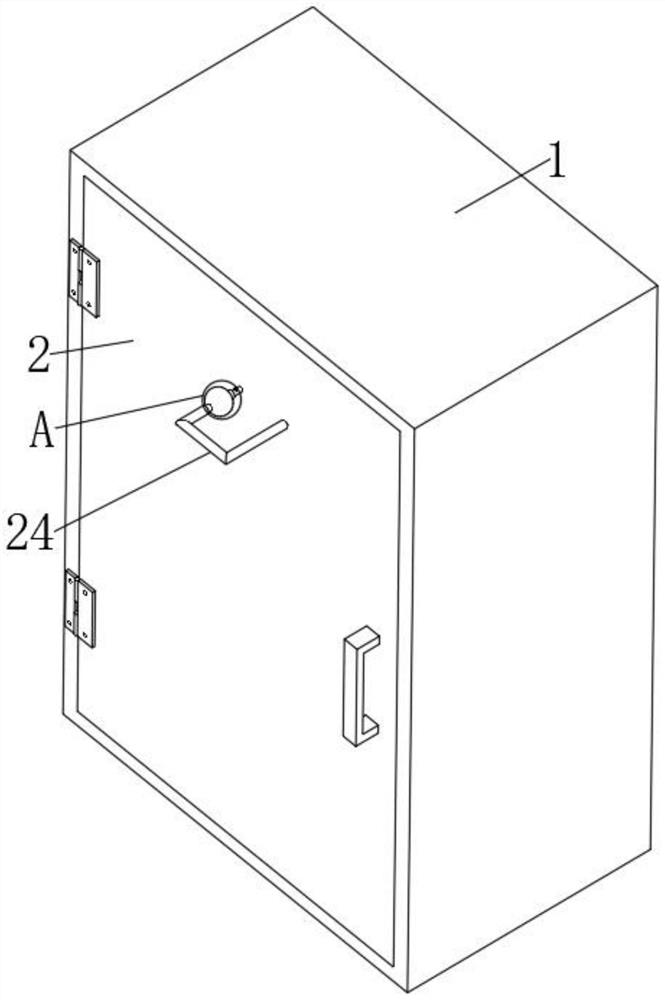
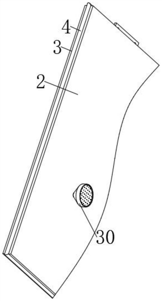
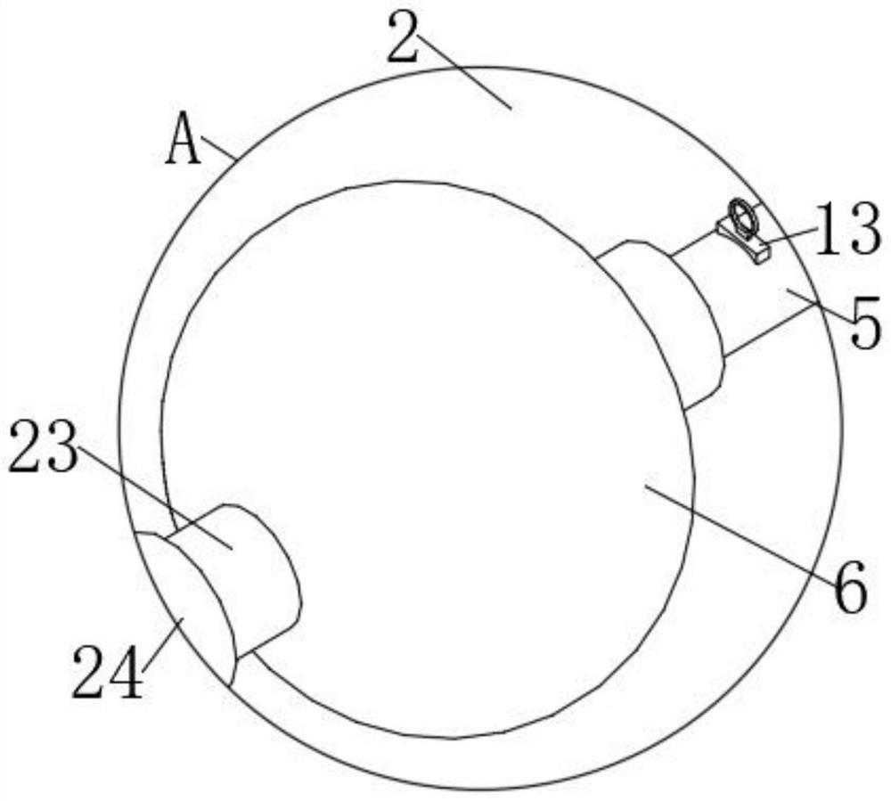
[0037] refer to Figure 1-7, an energy-saving and low-noise PLC control cabinet, comprising a cabinet body 1, a cabinet door 2 is hinged at the front end of the cabinet body 1, and the outer wall around the cabinet door 2 is provided with the same installation groove 3, and an inflatable hose 4 is bonded in the installation groove 3, The front end of the cabinet door 2 is fixed with a first branch pipe 5, the top of the first branch pipe 5 communicates with the inflation hose 4, the first branch pipe 5 is fixed with an anti-slip collar 22, and the front end of the first branch pipe 5 is covered with a balloon 6. The front end of the balloon 6 is bonded with a second branch pipe 23, and the front end of the second branch pipe 23 is connected with a connecting pipe 24, and the other side of the connecting pipe 24 is fixed through the cabinet door 2, and the inner walls on both sides of the second branch pipe 23 are provided with a second chute 25. A second slide block 26 is slid...

Embodiment 2

[0044] refer to Figure 8-12 , an energy-saving and low-noise PLC control cabinet, the rear end of the cabinet door 2 is fixed with a draft cover 30 by bolts, the draft cover 30 is arranged in a funnel shape, the draft cover 30 communicates with the connecting pipe 24, and the inner walls of the two sides of the draft cover 30 The same horizontal plate 31 is fixed between them by bolts. The rear end of the horizontal plate 31 runs through and is connected to the second shaft 32 through bearing rotation. The front end of the second shaft 32 is fixed with a fan blade 33 by bolts. There is a screen 46 .

[0045] Further, the inner wall on both sides of the air induction cover 30 is provided with a third chute 43, and the third chute 43 is slidably connected with a third slider 44, and the third slider 44 and the inner wall of the third chute 43 are connected by bolts. The same third spring 45 is fixed, the mesh plate 46 is fixed between the two third sliders 44 by bolts, and the...


PUM


Abstract

The invention belongs to the technical field of PLC control cabinets, and particularly relates to an energy-saving low-noise PLC control cabinet which comprises a cabinet body, a cabinet door is hinged to the front end of the cabinet body, a mounting groove is formed in the outer wall of the periphery of the cabinet door, an inflation hose adheres to the interior of the mounting groove, a first branch pipe is fixed to the front end of the cabinet door in a penetrating mode, and the top of the first branch pipe communicates with the inflation hose. The front end of the first branch pipe is sleeved with a balloon, the front end of the balloon is bonded with a second branch pipe, the front end of the second branch pipe is communicated with a connecting pipe, second sliding grooves are formed in the inner walls of the two sides of the second branch pipe, second sliding blocks are slidably connected into the second sliding grooves, and second springs are fixed between the second sliding blocks and the inner walls of the rear ends of the second sliding grooves. An exhaust block is fixed between the two second sliding blocks, and exhaust holes are formed in the front end and one side of the exhaust block. According to the invention, air in the cabinet body is pumped into the inflation hose, the door crack is closed, noise transmission is reduced, and meanwhile, the air content in the cabinet body is reduced, so that effective noise reduction is carried out.

Description

technical field [0001] The invention relates to the technical field of PLC control cabinets, in particular to an energy-saving and low-noise PLC control cabinet. Background technique [0002] The PLC integrated control cabinet has protection functions such as overload, short circuit, and phase loss protection. It has compact structure, stable operation and complete functions. It can be combined according to the size of the actual control scale, which can not only realize the automatic control of a single cabinet, but also realize the distribution (DCS) control system composed of multiple cabinets through industrial Ethernet or industrial field bus network. PLC control cabinets can adapt to industrial automation control occasions of various sizes. Widely used in electric power, metallurgy, chemical industry, papermaking, environmental protection sewage treatment and other industries. [0003] PLC control cabinets are generally equipped with cabinet doors, and the cabinet d...

Claims


Application Information

Patent Timeline
Patent Type & Authority Applications(China)
IPC IPC(8): H05K5/02H05K5/06B01D46/76B01D46/10
CPCH05K5/0217H05K5/0213H05K5/067B01D46/10
Inventor 支博文
Owner 支博文
Why Eureka
Try Eureka