Planetary gear transmission and wind power generation equipment with same

A technology of planetary gear transmission and planetary gear, which is applied in the direction of gear transmission, transmission, transmission parts, etc., can solve the problems of high cost and achieve the effect of increasing the tilt clearance

Inactive Publication Date: 2018-01-23
ZF FRIEDRICHSHAFEN AG
View PDF10 Cites 0 Cited by
  • Summary
  • Abstract
  • Description
  • Claims
  • Application Information

AI Technical Summary

Problems solved by technology

The disadvantage of this known solution is that the bearing clearance of the tapered roller bearing can only be adjusted very cost-effectively by cutting or grinding methods

Method used


Image

  • Planetary gear transmission and wind power generation equipment with same
  • Planetary gear transmission and wind power generation equipment with same
  • Planetary gear transmission and wind power generation equipment with same

Examples


Embodiment Construction

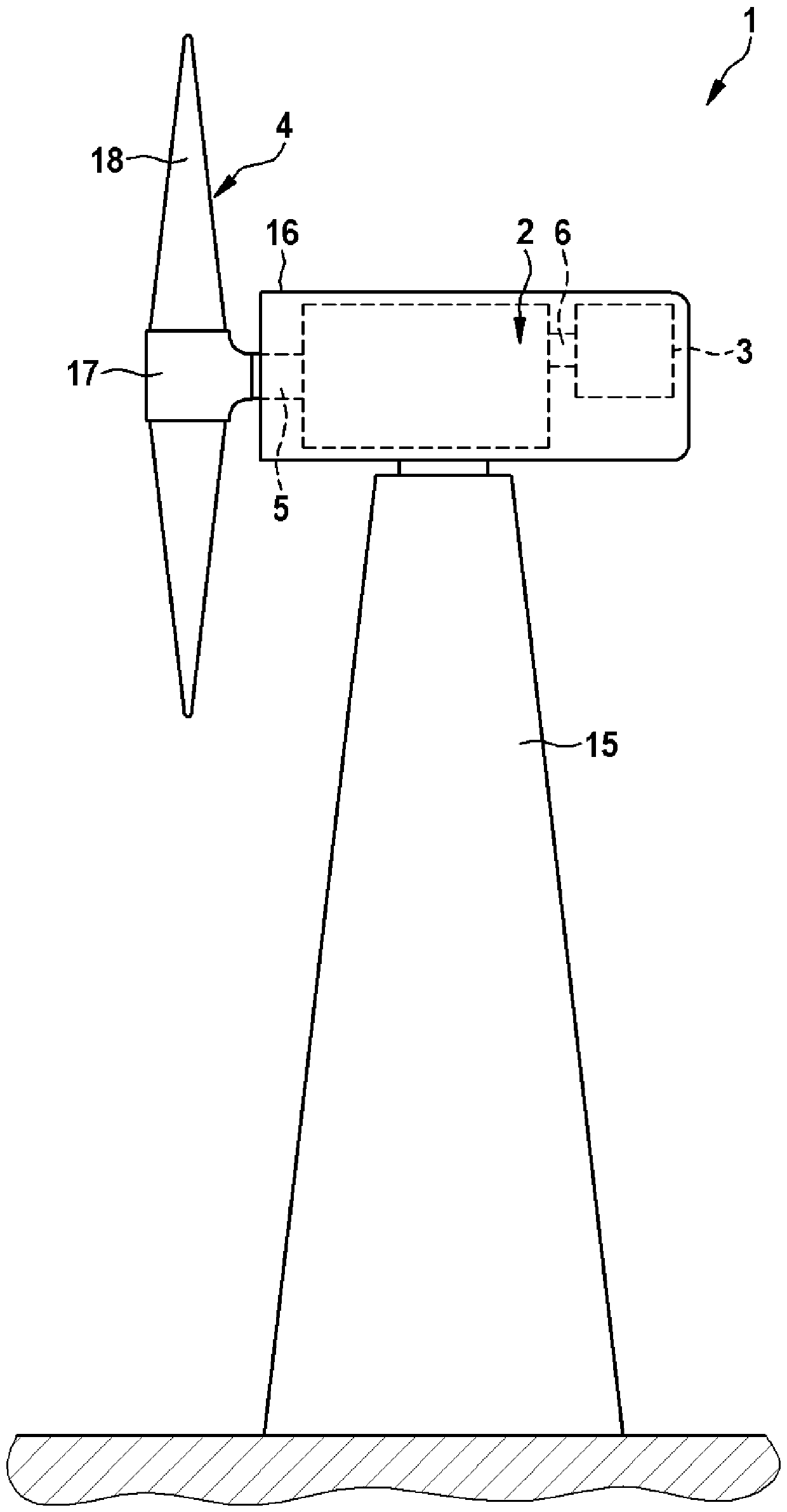
[0021] figure 1 A side view of the wind power plant 1 with its basic components is shown. The wind power plant 1 has a tower 15 on which a nacelle 16 in the form of a machine housing is arranged so as to be rotatable about a vertical axis. A planetary gear 2 is fastened in the gondola 16 in a rotationally fixed manner, wherein the planetary gear 2 has a drive shaft 5 and an output shaft 6 . The drive shaft 5 of the planetary gear 2 is connected to a hub 17 of a rotor 4 with a plurality of rotor blades 18 . The driven shaft 6 is connected in rotation to a drive to be driven in the form of a generator 3 .

[0022] The planetary gear 2 is designed such that it converts a slow rotation of the drive shaft 5 into a fast rotation of the output shaft 6 . To this end, the planetary gear 2 has one or more planetary gear stages, which interact with the output shaft 6 via a closed spur gear. Electric energy is generated by means of a wind power plant 1 by introducing the rotation, wh...


PUM


Abstract

A planetary gear transmission for converting slow rotation of a drive shaft into a fast rotation of a driven shaft, the planetary gear transmission has a bearing mechanism for rotatably supporting planetary gears on a planetary gear carrier, comprising at least two a tapered roller bearing arranged between the planetary gear and the planetary gear carrier, at least two tapered roller bearings respectively have an inner ring and an outer ring, and are arranged between the two inner rings on the outer circumferential surface of the planetary gear carrier There are washers for axially positioning at least two tapered roller bearings on the planetary carrier, on the inner peripheral surface of the planetary gear between the two outer rings radially along the inner circumference of the planetary gear there is a spacer for axial fixing The flange of the planetary gear, and at least one washer for mutual axial positioning of at least two tapered roller bearings is arranged on the inner circumferential surface of the planetary gear, at least one washer has a directed flange on the outer circumferential surface and is at least equivalent to Clearance for the axial length of the flange.

Description

technical field [0001] The invention relates to a planetary gear for converting a slow rotation of a drive shaft into a fast rotation of a driven shaft, wherein the planetary gear has bearings on a planet carrier for rotatably mounting planet gears mechanism, the bearing mechanism includes at least two tapered roller bearings arranged axially apart from each other between the planetary gear and the planetary gear carrier, wherein the at least two tapered roller bearings each have an inner ring and an outer ring, and a washer is arranged between the two inner rings on the outer peripheral surface of the planetary gear carrier, and the washer is used to axially locate the at least two tapered roller bearings in the On the planet gear carrier, wherein a flange is also formed on the inner peripheral surface of the planet gear radially along the inner circumference of the planet gear between the two outer rings, the flange is used for The planetary gears are fixed axially. [000...

Claims


Application Information

Patent Timeline
Patent Type & Authority Patents(China)
IPC IPC(8): F16H57/08F03D13/20F16C19/54F16C19/22
CPCF16C19/542F16H57/08F16H2057/085Y02E10/72F05B2260/40311F16C35/067F16C19/543F16C2361/61F03D15/00F16C19/364F16C2360/31F03D15/10F03D80/70F16H1/2809
Inventor D.魏斯特
Owner ZF FRIEDRICHSHAFEN AG
Why Eureka
Try Eureka