Gearbox drive unit

A technology for drive units and transmission components, applied in the direction of transmissions, gear transmissions, components with teeth, etc., can solve problems such as limitations, and achieve the effects of load reduction and load capacity improvement

Inactive Publication Date: 2011-06-08
ROBERT BOSCH GMBH
View PDF5 Cites 2 Cited by
  • Summary
  • Abstract
  • Description
  • Claims
  • Application Information

AI Technical Summary

Problems solved by technology

This limits the choice of materials that must also meet other requirements

Method used


Image

  • Gearbox drive unit
  • Gearbox drive unit
  • Gearbox drive unit

Examples


Embodiment Construction

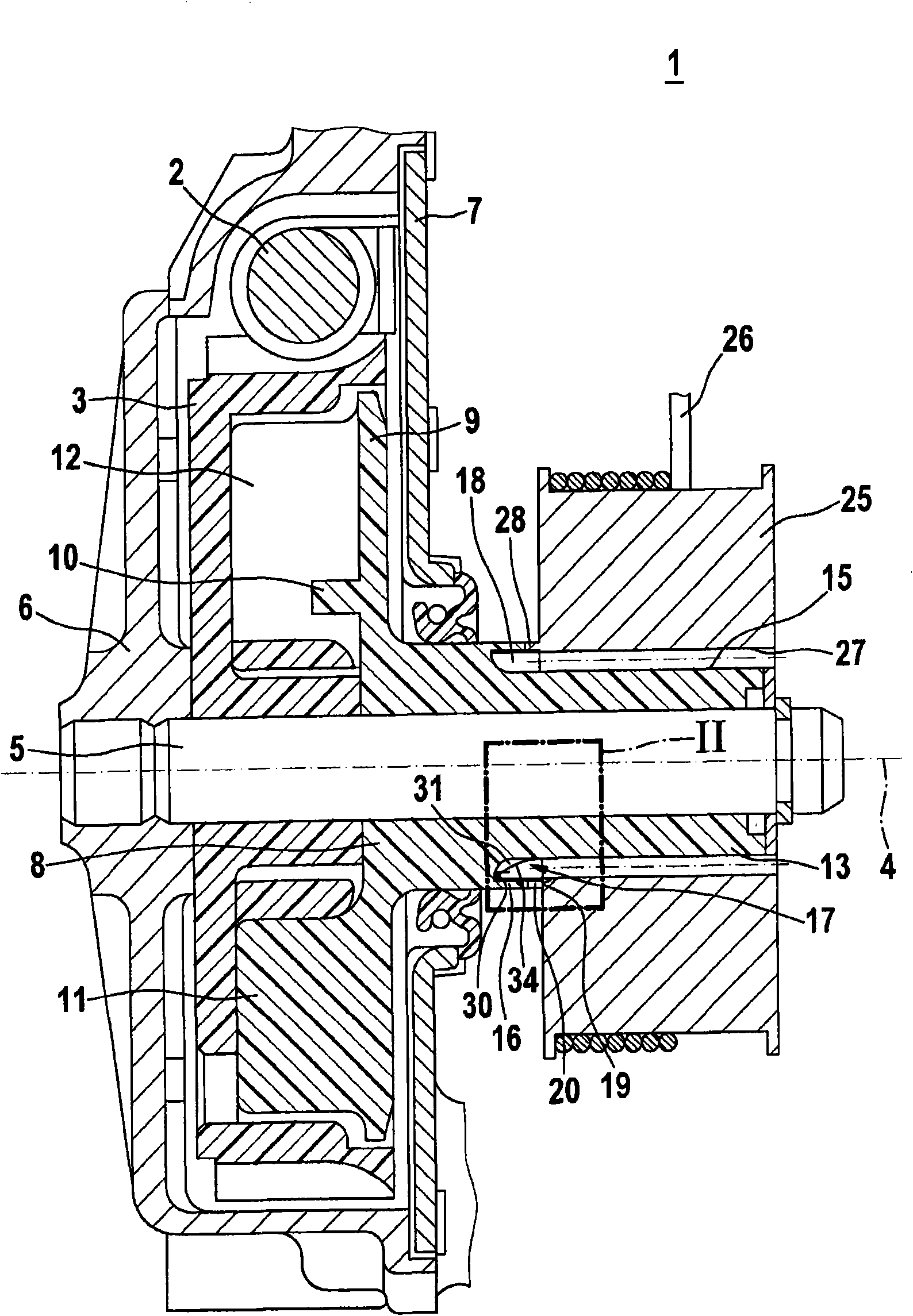
[0018] figure 1 A schematic partial cross-sectional view of the transmission-drive unit 1 of the first embodiment is shown. This transmission-drive unit 1 can be used in particular as an auxiliary drive for assisted operation adjustment or for supporting adjustment of automobile components. For example, the transmission-drive unit 1 can be used to adjust a car window or a car sunroof. However, the transmission-drive unit 1 according to the invention is also suitable for other use cases.

[0019] The transmission-drive unit 1 has a worm shaft 2. This worm shaft is designed, for example, as an extension of the armature shaft of the drive motor. The worm shaft 2 and a worm gear 3 work together. The transmission-drive unit 1 has a rotation axis 4 around which the worm gear 3 driven during operation rotates. In this case, the direction of rotation can be specified by the direction of rotation of the worm shaft 2. In this way, this worm gear 3 can be driven purposefully according ...


PUM


Abstract

The invention relates to a gearbox drive unit, particularly to a gearbox drive unit serving as an electrical auxiliary drive for motor vehicle. The gearbox drive unit comprises a rotatably arranged gearbox element (8), in which external teeth (15) and an annular collar (16) are formed. The annular collar (16) sectionally surrounds the external teeth (15) along a rotational axis (4). A frontal toothing (20) is formed on the annular collar (16). The external teeth (15) is designed into modifiable fine teeth, and the frontal toothing (20) of the annular collar (16) is formed by a pointed tooth crown (20).

Description

Technical field [0001] The invention relates to a transmission-drive unit, in particular to an electric auxiliary drive device for automobiles. The present invention particularly relates to the field of electric auxiliary drive devices for assisting operation adjustment or supporting adjustment of automobile parts. Background technique [0002] DE 10228705 A1 discloses a transmission-drive part for regulating moving parts in a motor vehicle. The disclosed transmission-drive unit includes a gear having an external toothing portion and a base. Its outer diameter is larger than that of the outer teeth. The base includes a circumferential axial groove. The external teeth extend into this groove. [0003] The transmission-drive unit disclosed in DE 10228705A1 has the disadvantage that the load on the external toothing is relatively large. Therefore, for gears, relatively strong materials are required in terms of the loads that occur in the corresponding use situation. This limits ...

Claims


Application Information

Patent Timeline
Patent Type & Authority Applications(China)
IPC IPC(8): F16H55/17F16D1/10
CPCF16H1/16F16D2001/103F16D1/076
Inventor M・费德勒
Owner ROBERT BOSCH GMBH
Why Eureka
Try Eureka