
A planetary wheel shaft for planetary row load equalization

A planetary axle and planetary row technology, applied in the direction of gear lubrication/cooling, belt/chain/gear, transmission parts, etc., can solve the problem of planetary row planetary gear transmission life and reliability, friction plates, gears and other parts damage , increased vibration of friction plates, etc., to achieve the effect of improving excessive dynamic load, improving life and reliability, and avoiding excessive meshing dynamic load

Inactive Publication Date: 2016-02-03
CHINA NORTH VEHICLE RES INST
View PDF7 Cites 0 Cited by
  • Summary
  • Abstract
  • Description
  • Claims
  • Application Information

AI Technical Summary

Problems solved by technology

[0002] At present, in the design of the planetary row of domestic high-power planetary gearboxes, the planetary gear shafts are all rigid and solid. Due to the excessive rigidity, this rigid structure is very important for adjusting dynamic loads, errors and misalignment during processing and assembly. The dynamic load and vibration problems caused by various aspects such as load, uneven load between planetary gears and the up and down fluctuation of the outer friction plate of the ring gear are very unfavorable, especially when the speed is above 3000 rpm, the vibration and noise of the gearbox will increase with the speed. When the input physical parameters such as oil pressure, external load and other factors change, sometimes it will cause severe vibration of friction plates and various components in the planetary row or the dynamic load is too large. In severe cases, the entire planetary row and ring gear The vibration of the outer friction plate is intensified, causing damage to the friction plate, gears and other components, affecting the life and reliability of the entire planetary row and even the planetary gear transmission

Method used


Image

  • A planetary wheel shaft for planetary row load equalization

Examples


Embodiment Construction

[0014] In order to make the purpose, content and advantages of the present invention clearer, the specific implementation manners of the present invention will be further described in detail below in conjunction with the accompanying drawings and embodiments.

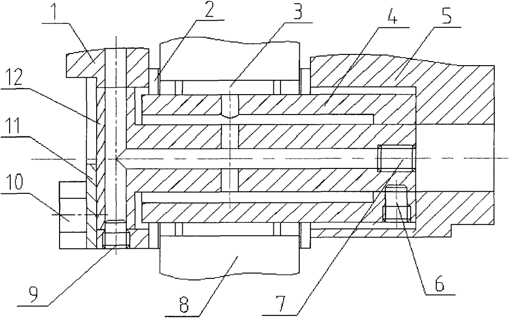
[0015] Such as figure 1 As shown, the planetary gear shaft provided by the present invention for planetary row load equalization is assembled in the transmission, and the planetary gear shaft is composed of a U-shaped shaft 4 and a T-shaped shaft 12, and the U-shaped shaft 4 and the T-shaped shaft 12 are connected by set screws 6 Axially fixed, the oil plug 7 seals the right end of the lubricating oil channel of the T-shaped shaft 12, and the T-shaped shaft 12 is axially fixed on the sub-frame 1 by the set screw 9.

[0016] The U-shaped shaft 4 is designed as a U-shaped structure with a columnar thin-walled interior, and its left end is pushed against the inner hole of the main frame 5, and the inner end of the U-shaped...


PUM


Abstract

The invention belongs to the technical field of mechanical transmission, and relates to a planet wheel shaft used for uniform loading of a planet row. The planet wheel shaft used for uniform loading of the planet row achieves the purpose that a plurality of planet wheels can coordinate with one another and realize uniform and large loads under the condition of uneven loads. The planet wheel shaft used for uniform loading of the planet row is composed of a U-shaped shaft and a T-shaped shaft, wherein the U-shaped shaft and the T-shaped shaft are axially fixed together through a positioning screw, the right end of a lubricating oil passage of the T-shaped shaft is sealed through an oil plug, the T-shaped shaft is axially fixed on a secondary framework through the positioning screw, and an interval exists between an inlet end of the U-shaped shaft and a right angle shape bottom of the T-shaped shaft. The planet wheel shaft used for uniform loading of the planet row provides a deformation space for the loaded U-shaped shaft by utilizing the interval between the U-shaped shaft and the T-shaped shaft, and enables the planet wheels to coordinate with one another and realize uniform and large loads under the condition of uneven loads, thereby restraining overlarge loads of several planet wheels, lowering the dynamic load amplitude, achieving the purposes of vibration and noise reduction, prolonging the service life of the entire planet wheel row and planetary gears in transmission, and improving the reliability of the entire planet wheel row and the planetary gears in transmission.

Description

technical field [0001] The invention belongs to the technical field of mechanical transmission, and in particular relates to a planetary gear shaft used for load balancing of planetary rows. Background technique [0002] At present, in the design of the planetary row of domestic high-power planetary gearboxes, the planetary gear shafts are all rigid and solid. Due to the excessive rigidity, this rigid structure is very important for adjusting dynamic loads, errors and misalignment during processing and assembly. The dynamic load and vibration problems caused by various aspects such as load, uneven load between planetary gears and the up and down fluctuation of the outer friction plate of the ring gear are very unfavorable, especially when the speed is above 3000 rpm, the vibration and noise of the gearbox will increase with the speed. When the input physical parameters such as oil pressure, external load and other factors change, sometimes it will cause severe vibration of f...

Claims


Application Information

Patent Timeline
Patent Type & Authority Patents(China)
IPC IPC(8): F16H57/08F16H57/04
CPCF16H57/0423F16H57/08
Inventor 尹华兵李慎龙周广明赵欣源张鹤张静邢庆坤
Owner CHINA NORTH VEHICLE RES INST
Learn More