Tripod

A tripod and tray technology, applied in the field of tripods, can solve the problems of instrument damage, limited functions, waste of personnel, etc., and achieve the effects of ensuring stability, accurate surveying and mapping, and saving personnel resources.

Inactive Publication Date: 2014-01-15
卢传宇
View PDF0 Cites 3 Cited by
  • Summary
  • Abstract
  • Description
  • Claims
  • Application Information

AI Technical Summary

Problems solved by technology

[0003] A tripod is a tool that people who need surveying and mapping need to use when working outdoors. It is very convenient to use a tripod to fix products such as cameras, levels, theodolites, and total stations. It is also an important additional hardware. The existing triangle There are many shapes of frames, but their functions are limited. Most of people’s surveying and mapping work is in the open air, and they often fix the instruments exposed on the tripod. Except for the fixing function, the tripod cannot provide other protection functions, so that strong sunlight or rain will Direct contact with the instrument will cause damage to the instrument. Sometimes the sun is too strong, which will also affect the measurement accuracy of the instrument. Therefore, it is often necessary to open an umbrella for the tool alone when working, which is a waste of personnel and is inconvenient. , affecting the normal measurement work, in order to solve this problem, it is necessary to produce a tripod with a protective umbrella, so that the measurement work can be performed well without the influence of the sun, and personnel resources can be saved. Fixing the umbrella needs to take into account that the sun and rain sometimes come from different directions. How to fix the umbrella and how to adjust the angle of the umbrella so that it can well block the sun and rain are issues that need to be considered

Method used


Image

  • Tripod

Examples


Embodiment Construction

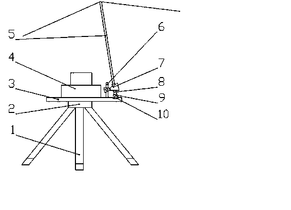
[0009] Refer to attached figure 1 As follows: a tripod, including leg 1, connecting plate 2, tray 3, instrument 4, umbrella 5, support column 6, clip 7, umbrella handle 8, inserting column 9 and rotating wheel 10, is characterized by hard The lower part of the tray 3 is fixedly connected with the connection plate 2, and the lower part of the connection plate 2 is rotatably connected with the outrigger 1 which can be extended and closed for supporting and fixing, so that it can stand stably on the ground for accurate measurement. The upper part is fixed with an instrument 4 for measurement, and the upper edge of the tray 3 is fixedly connected with a vertical support column 6 upwards. The upper part of the support column 6 is connected with a clip 7 through a rotating shaft. The structure of the umbrella handle 8 of 5, the lower part of the umbrella handle 8 of the umbrella 5 is fixed by the clip 7 and then the protruding part is inserted in the hollow post 9, and the bottom of...


PUM


Abstract

The invention relates to a tripod which comprises supporting legs, a connecting disc, a tray, an instrument, an umbrella, a supporting column, a clamp, an umbrella handle, an inserting column and a rotary wheel. The tripod is characterized in that the connecting disc is fixedly connected to the lower portion of the hard tray, the supporting legs capable of being unfolded and folded and achieving the supporting and fixing functions are connected to the lower portion of the connecting disc in a rotary mode, the instrument used for measurement is fixed to the upper portion of the tray, the edge of the upper face of the tray is fixedly connected with the perpendicular supporting column in the upward direction, the clamp is connected to the upper portion of the supporting column in a rotary mode through a rotary shaft, two clamping openings of the clamp are respectively of the structure that the two clamping openings can clamp the umbrella handle of the umbrella in a matched mode, after the lower portion of the umbrella handle of the umbrella is fixed through the clamp, the extending portion is inserted in the hollow inserting column, the bottom of the inserting column matched with the umbrella handle in size is connected with the edge of the tray in a rotary mode through the rotary wheel, so that the umbrella handle is fixed to the inner portion of the clamp, supported by the tray and stabilized at two points, and therefore the measurement instrument is protected against damage of rainwater and sunshine. The tripod is simple in structure and easy to manufacture.

Description

[0001] technical field [0002] The invention relates to a surveying and mapping product, more precisely a tripod. Background technique [0003] A tripod is a tool that people who need surveying and mapping need to use when working outdoors. It is very convenient to use a tripod to fix products such as cameras, levels, theodolites, and total stations. It is also an important additional hardware. The existing triangle There are many shapes of frames, but their functions are limited. Most of people’s surveying and mapping work is in the open air, and they often fix the instruments exposed on the tripod. Except for the fixing function, the tripod cannot provide other protection functions, so that strong sunlight or rain will Direct contact with the instrument will cause damage to the instrument. Sometimes the sun is too strong, which will also affect the measurement accuracy of the instrument. Therefore, it is often necessary to open an umbrella for the tool alone when working,...

Claims


Application Information

Patent Timeline
Patent Type & Authority Applications(China)
IPC IPC(8): F16M11/20F16M11/04G01C15/00
Inventor 卢传宇
Owner 卢传宇
Why Eureka
Try Eureka