Shaft, particularly a cam shaft, comprising a hollow shaft section

A technology for hollow shafts and camshafts, which is applied to shafts including hollow shaft sections, especially in the field of camshafts, which can solve the problems of incomplete anti-splashing and structural space consumption of pre-separators, and achieve the goal of preventing oil intrusion Effect

Active Publication Date: 2013-11-27
THYSSENKRUPP PRESTA TECCENTER AG
View PDF7 Cites 2 Cited by
  • Summary
  • Abstract
  • Description
  • Claims
  • Application Information

AI Technical Summary

Problems solved by technology

However, the role as anti-splash is incomplete, because oil droplets or oil jets sprayed obliquely cannot be blocked
The construction of the pre-separator is also relatively complex and requires considerable installation space

Method used


Image

  • Shaft, particularly a cam shaft, comprising a hollow shaft section
  • Shaft, particularly a cam shaft, comprising a hollow shaft section
  • Shaft, particularly a cam shaft, comprising a hollow shaft section

Examples


Embodiment Construction

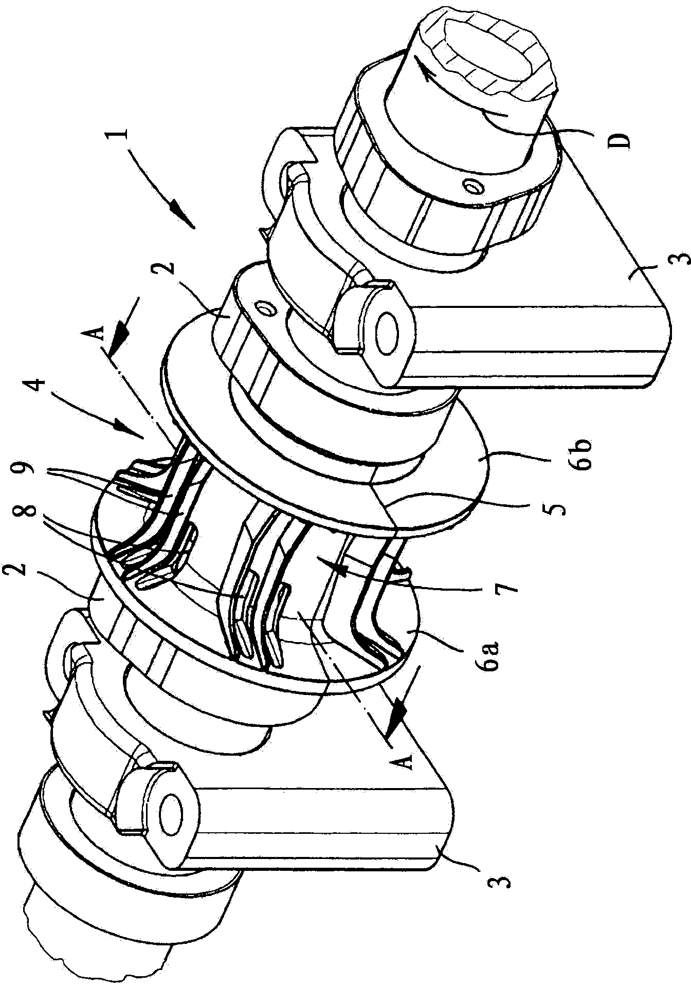
[0028] figure 1 The completed assembled camshaft module is shown, comprising a camshaft 1 which, according to its usual design, has a plurality of cams 2 and which is supported by a bearing block 3 . Between two adjacent cams 2 there is a splash guard 4 , the functional principle of which will be explained in detail below.

[0029] here from figure 1It can be seen that the splash guard 4 is composed of two parts on a boundary surface 5 . It can also be seen that the splash guard 4 has flange-shaped widened ends 6 a , 6 b and a sleeve-shaped, substantially cylindrical middle section 7 lying between them. Visible in the central section are openings 8 in the form of longitudinal slots and projections in the form of ribs 9 which extend in the longitudinal direction of the shaft.

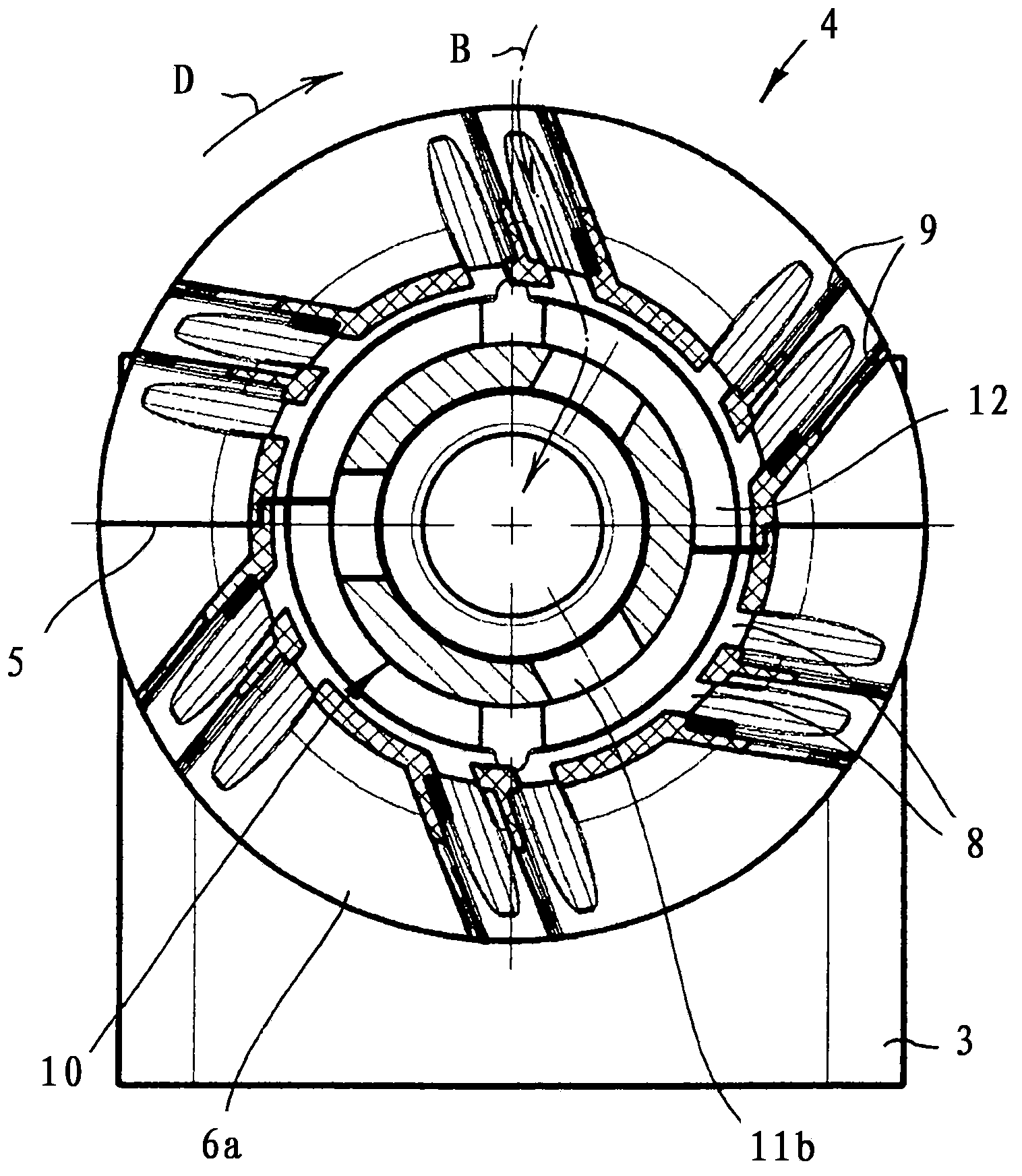
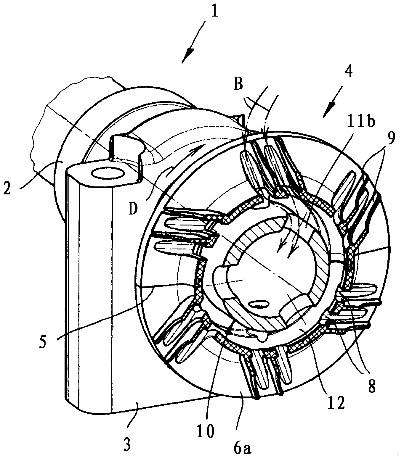
[0030] The purpose of the anti-splash device 4 and the precise design structure of the camshaft 1 from Figures 2 to 4 obtained from the view. here, figure 2 and 3 shows a similar cross-section, ...


PUM


Abstract

The invention relates to a shaft, particularly a cam shaft (1), comprising a hollow shaft section (10) with at least one radial inlet opening (11a, 11b) for evacuating a gas through said hollow shaft section (10), and comprising a splash-guard device (4) arranged in the region of the radial inlet opening (11a, 11b) on the hollow shaft section (10). According to the invention, the splash-guard device (4) has a radially exposed cover with radial passage openings (8) and protrusions between said passage openings (8). The protrusions can, in particular, be in the form of ribs (9). To be published with figure 3.

Description

technical field [0001] The invention relates to a shaft, in particular a camshaft, comprising a hollow shaft section with at least one radial inlet opening for exhaust gas through the hollow shaft section and a splash guard, the splash guard The device is arranged in the region of the radial access opening on the hollow shaft section. Background technique [0002] Leakage losses are noted in practice in internal combustion engines and piston compressors, which are attributable to incomplete seals. These leakage losses are known as blow-by and contain a significant oil component. For internal combustion engines it is therefore customary to guide the blow-by gases occurring in the valve chambers back into the intake tract of the internal combustion engine. In order to minimize oil losses due to blow-by gases on the one hand and to ensure optimized combustion with minimal environmental impact on the other hand, it is known to separate oil from the blow-by gases and to return ...

Claims


Application Information

Patent Timeline
Patent Type & Authority Applications(China)
IPC IPC(8): F01L1/047F01L1/46F01M13/04
CPCF01L2001/0475F01M2013/0422F01L1/46F01L1/047F01M13/04F02B67/06F01L2001/0476Y10T74/2101
Inventor U·米勒
Owner THYSSENKRUPP PRESTA TECCENTER AG
Why Eureka
Try Eureka