Dust falling device for architectural engineering

A technology of dust suppression device and construction engineering, which is applied in the directions of spray device, use of liquid separation agent, dispersion particle separation, etc. Guaranteed efficiency and increased range effects

Active Publication Date: 2020-08-07
河南图强建筑工程有限公司
View PDF8 Cites 1 Cited by
  • Summary
  • Abstract
  • Description
  • Claims
  • Application Information

AI Technical Summary

Problems solved by technology

[0003] Chinese Patent No. CN206844663U discloses a dust suppression device for construction engineering, including a fog cannon, a support base, a fixed hoop, a driving gear and a rotating shaft. Support rods are installed on both sides of the fog cannon, and a fixed base, a fixed base is installed on the upper side of the support base, and a main bracket is fixed below the support base, a water pump is arranged on the lower right side of the main bracket, and a rotating shaft is also installed between the fixed base and the support base, The convenient device changes the working direction of the fog cannon with the change of the dust source, the lifting effect of the fog cannon is poor, and the spraying of the fog cannon is small, resulting in unsatisfactory dust reduction effect
[0004] Chinese Patent No. CN207775802U discloses a dust suppression device for construction engineering, including a base, a rotating motor, a supporting plate, a water storage tank, a water pump, a pole, a carrier plate and a mounting box, and the upper wall of the base is provided with a mounting groove. The rotating motor is placed in the installation groove, the supporting plate is placed on the driving end of the rotating motor, the water storage tank is placed on the supporting plate, and the water pump is placed in the water storage tank. Protective spray nozzles, construction site dust is easy to block the spray nozzles, affecting the effect of dust reduction

Method used


Image

  • Dust falling device for architectural engineering
  • Dust falling device for architectural engineering
  • Dust falling device for architectural engineering

Examples


Embodiment

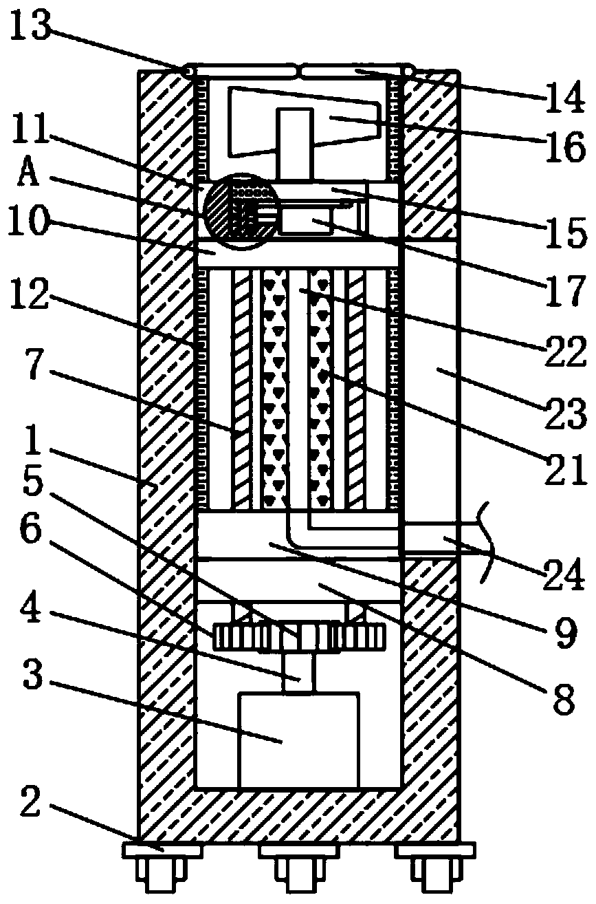
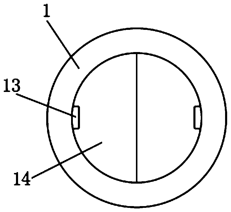
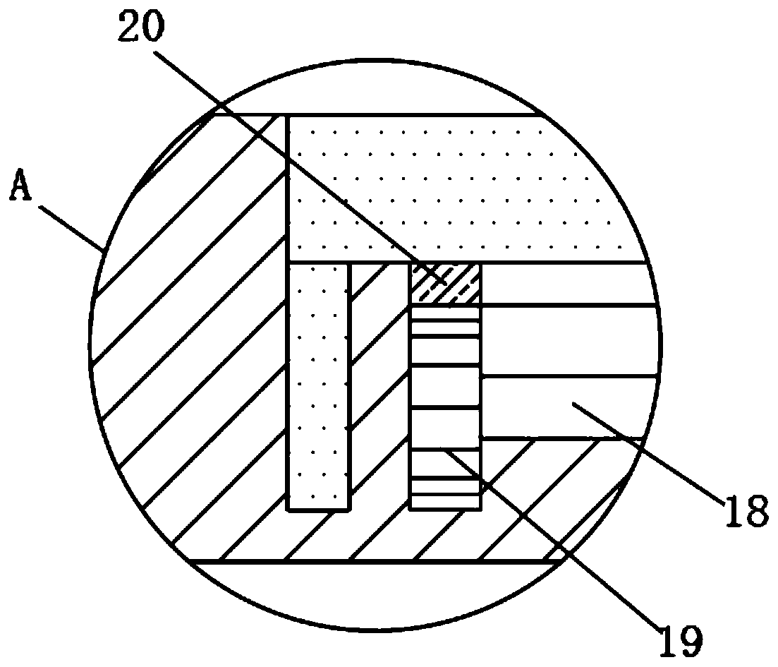
[0022] see Figure 1-6 , the present invention provides a technical solution: a dust suppression device for construction engineering, including a housing 1, the bottom of the inner wall of the housing 1 is fixedly connected with a first motor 3, and the top output shaft of the first motor 3 is welded with a first rotating shaft 4. The top of the first rotating shaft 4 is welded with a driving gear 5, and the outer wall of the driving gear 5 is meshed with three driven gears 6 distributed in a ring with the center point of the driving gear 5 as the center of the circle. The driven gear 6 The top center of the housing 1 is welded with a screw rod 7, the inner side wall of the housing 1 is welded with a chassis 8, the inner side wall of the housing 1 is slidably connected with a lifting plate 9, the inner side wall of the housing 1 is welded with a fixed plate 10, and the inner side of the housing 1 The wall is slidingly connected with a circular base 11, the circular base 11 is ...


PUM


Abstract

The invention discloses a dust falling device for architectural engineering. The dust falling device for architectural engineering comprises a shell, wherein a first motor is fixedly connected to thebottom part of the inner side wall of the shell; a first rotary shaft is welded to an output shaft on the top part of the first motor; a driving gear is welded to the top part of the first rotary shaft; three driven gears distributed annularly by adopting a center point of the driving gear as a circle center are connected to the outer side wall of the driving gear in a meshing way; screw rods arewelded to the centers of the top parts of the driven gears; and a chassis is welded to the inner side wall of the shell. The first motor drives the screw rods to rotate so as to further drive a lifting plate and a circular base to raise or lower; due to the arrangement of a lifting rod, a lifting range of a fog gun is wider, so that a dust falling range of the fog gun is increased, the device canbe adaptive to different working environment, and a dust falling effect is improved; and meanwhile, due to the arrangement of a baffle plate, before the device works, the baffle plate can effectivelyblock dust of a construction site so as to prevent the dust from entering the fog gun, so that the dust falling efficiency is ensured.

Description

technical field [0001] The invention relates to the technical field of construction engineering, in particular to a dust suppression device for construction engineering. Background technique [0002] Construction engineering refers to the engineering entity formed through the construction of various housing buildings and their ancillary facilities and the installation activities of supporting lines, pipelines and equipment. Often, during the construction of a construction project, the dust generated is relatively large, and it is necessary to use a dust suppression device to remove the dust. [0003] Chinese Patent No. CN206844663U discloses a dust suppression device for construction engineering, including a fog cannon, a support base, a fixed hoop, a driving gear and a rotating shaft. Support rods are installed on both sides of the fog cannon, and a fixed base, a fixed base is installed on the upper side of the support base, and a main bracket is fixed below the support ba...

Claims


Application Information

Patent Timeline
Patent Type & Authority Applications(China)
IPC IPC(8): B05B15/68B05B15/62B05B12/16B05B15/50
CPCB01D47/06B05B12/16B05B15/50B05B15/62B05B15/68
Inventor 李文静
Owner 河南图强建筑工程有限公司
Why Eureka
Try Eureka