
led retrofit lamp

A technology of LED retrofit lamps and LED chips, which is applied in the use of semiconductor lamps, lighting devices, light sources, etc., can solve the problems of low integration, heavy lamp weight, and complexity.

Active Publication Date: 2017-05-31
LEDVANCE GMBH
View PDF4 Cites 0 Cited by
  • Summary
  • Abstract
  • Description
  • Claims
  • Application Information

AI Technical Summary

Problems solved by technology

However, this solution is too complicated, and the cost is high, and the weight of the lamp itself is too large
In addition, the driver is placed outside the lamp tube, and the integration level of the T8 retrofit lamp is relatively low, which is not conducive to replacing the conventional T8 lamp

Method used


Image

  • led retrofit lamp
  • led retrofit lamp
  • led retrofit lamp

Examples


Embodiment Construction

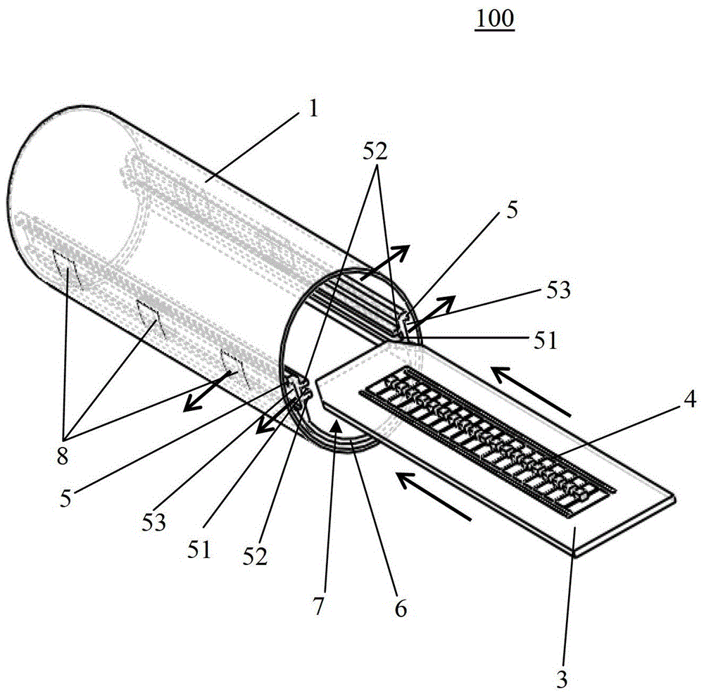
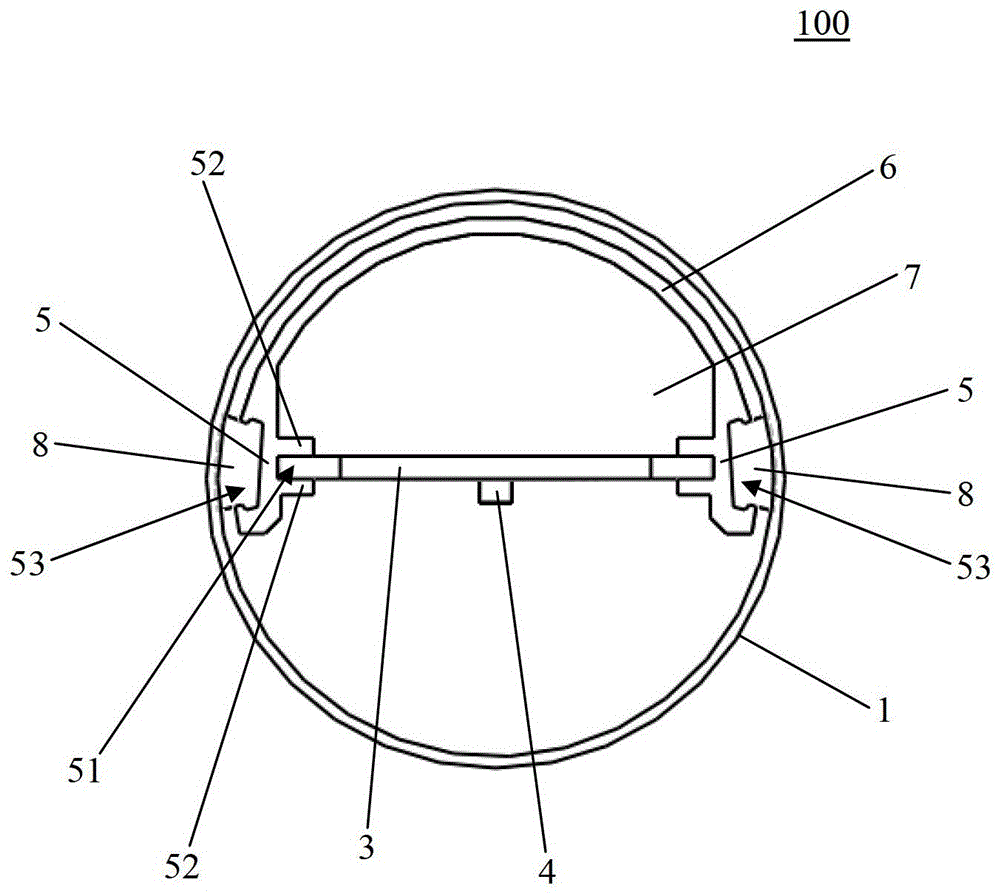
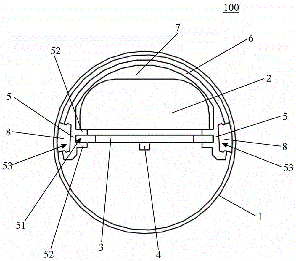
[0022] figure 1 A schematic diagram of the LED retrofit lamp 100 according to the present invention is shown. The LED retrofit lamp includes a lamp tube 1, an LED light-emitting engine and a driver 2 arranged in the lamp tube 1 (see image 3 ), the LED light engine includes a circuit board 3 and at least one LED chip 4 arranged on the circuit board 3, wherein the LED retrofit lamp 100 also includes a pair of fixing structures 5 arranged in the lamp tube 1, in other aspects of the present invention In an embodiment, multiple pairs of fixing structures 5 may also be provided. exist figure 1 In the schematic diagram shown, the circuit board 3 has not yet been inserted into the fixing structure 5 .

[0023] Additionally, from figure 1 It can be further seen in the figure that a guide groove 51 extending along the length of the fixing structure 5 is formed on the inner side of each fixing structure 5 . If so figure 1 The direction shown by the arrow in the circuit board 3 is ...


PUM


Abstract

The invention relates to an LED modification lamp (100) which comprises a lamp tube (1), an LED light-emitting engine and a driver (2), wherein the LED light-emitting engine and the driver (2) are arranged in the lamp tube (1), and the LED light-emitting engine comprises a circuit board (3) and at least one LED chip arranged on the circuit board (3). The LED modification lamp (100) further comprises at least one pair of fixing structures (5) arranged in the lamp tube (1). The circuit board (3) can be inserted into the fixing structures (5) along opposite edges, and the circuit board (3) is inserted into the fixing structures to drive the fixing structures to abut against the inner wall of the lamp tube (1) through certain stress.

Description

technical field [0001] The invention relates to an LED retrofit lamp. Background technique [0002] As we all know, LED lighting has irreplaceable advantages, such as energy saving, ultra-low power consumption, close to 100% electro-optical power conversion, the same lighting efficiency can save more than 80% energy than traditional light sources, and its life is longer. In view of the above advantages, more and more people use LEDs as light sources, such as a large number of LED retrofit lamps appearing on the market. This LED retrofit lamp has the outline of a traditional light source such as an incandescent lamp or a lamp tube, so that it can be used as a light source to better adapt to an existing lighting system. [0003] However, when replacing the traditional T8 type lamp, the circuit board on which the LED chip is arranged and the fixing of the driver in the glass tube become a prominent problem. This is because the traditional T8 type lamp has a glass tube. It is ...

Claims


Application Information

Patent Timeline
Patent Type & Authority Patents(China)
IPC IPC(8): F21K9/275F21V19/00F21V23/00F21Y115/10F21K9/00
CPCY02B20/30
Inventor 陈小棉李皓王雪峰林爱民
Owner LEDVANCE GMBH
Learn More