Winding and setting mechanism and timekeeper

A clockwork and barrel technology, applied in the field of clocks and watches, can solve the problems of inflexible operation, easy damage, and troublesome operation.

Active Publication Date: 2014-01-15
TIAN WANG ELECTRONICS (SHENZHEN) CO LTD
View PDF6 Cites 7 Cited by
  • Summary
  • Abstract
  • Description
  • Claims
  • Application Information

AI Technical Summary

Problems solved by technology

[0006] The object of the present invention is to provide a winding needle setting mechanism, aiming at solving the problem that the winding needle setting mechanism in the prior art is designed with a rod spring structure, which causes troublesome operation, easy damage, excessive volume, inflexible operation, unreliability and low efficiency. low problem

Method used


Image

  • Winding and setting mechanism and timekeeper
  • Winding and setting mechanism and timekeeper
  • Winding and setting mechanism and timekeeper

Examples


Embodiment 1

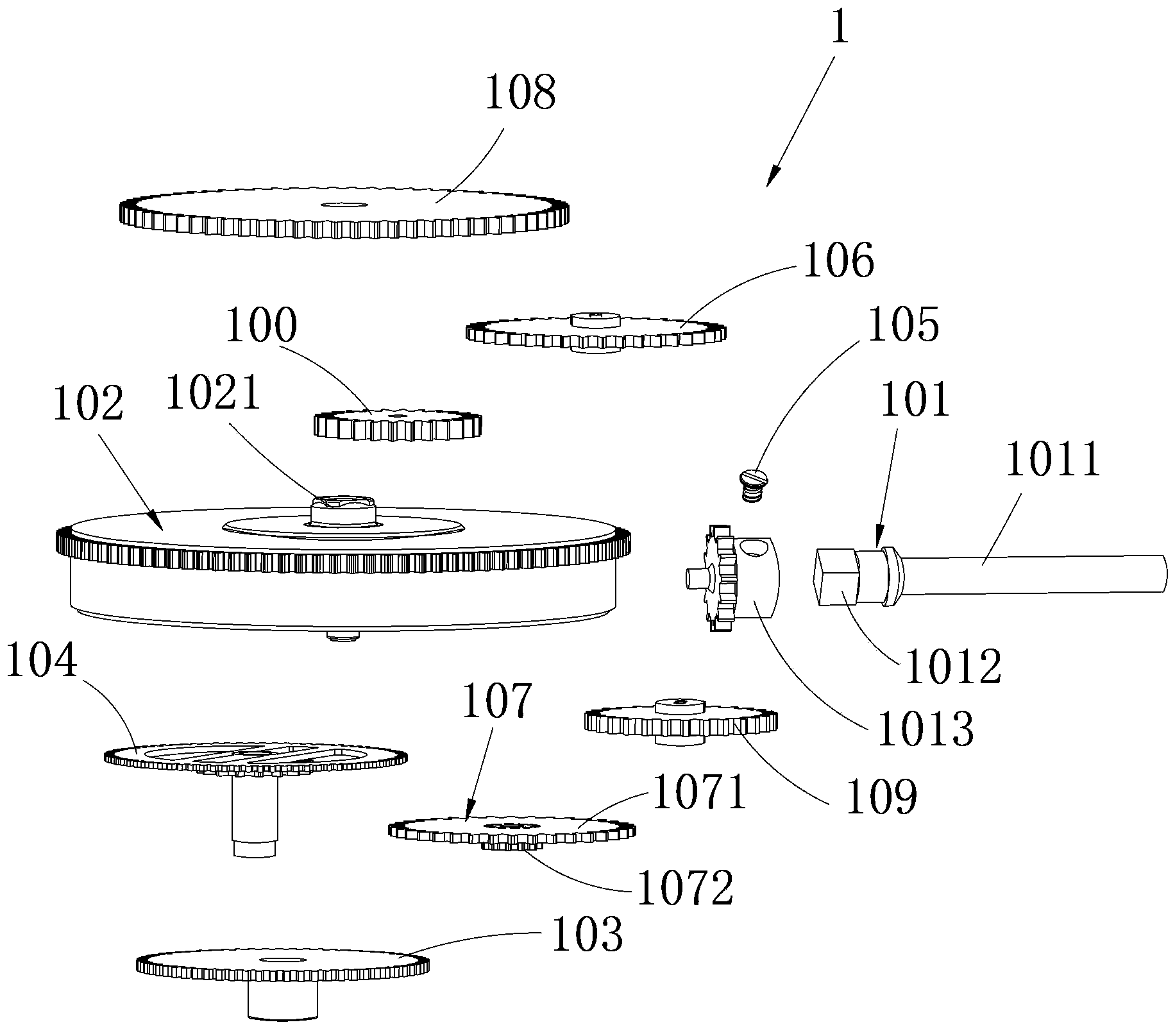
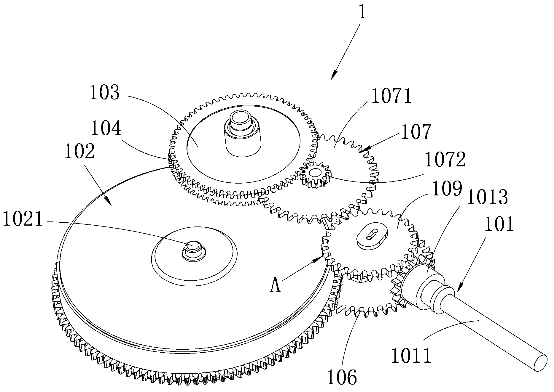
[0022] Such as Figure 1~4 Shown is a preferred embodiment provided by the present invention.

[0023] The winding needle setting mechanism 1 provided in this embodiment includes a rotatable stem 101, a barrel gear 102 with a mainspring inside, a minute gear 104, and an hour wheel 103 sleeved on the minute gear 104. The stem 101 One end is provided with a vertically arranged vertical gear 1013, the top of the vertical gear 1013 is provided with a first gear structure 106 that can be rotated by the vertical gear 1013 in the forward direction, and the bottom is provided with a gear structure 106 that can be rotated by the vertical gear 1013 in the reverse direction. The second gear structure 109 .

[0024] The first intermediate gear train is meshed between the first gear structure 106 above the vertical gear 1013 and the barrel gear 102. Only when the vertical gear 1013 rotates forward, the first intermediate gear train can be driven to rotate, that is: when When the first ge...

Embodiment 2

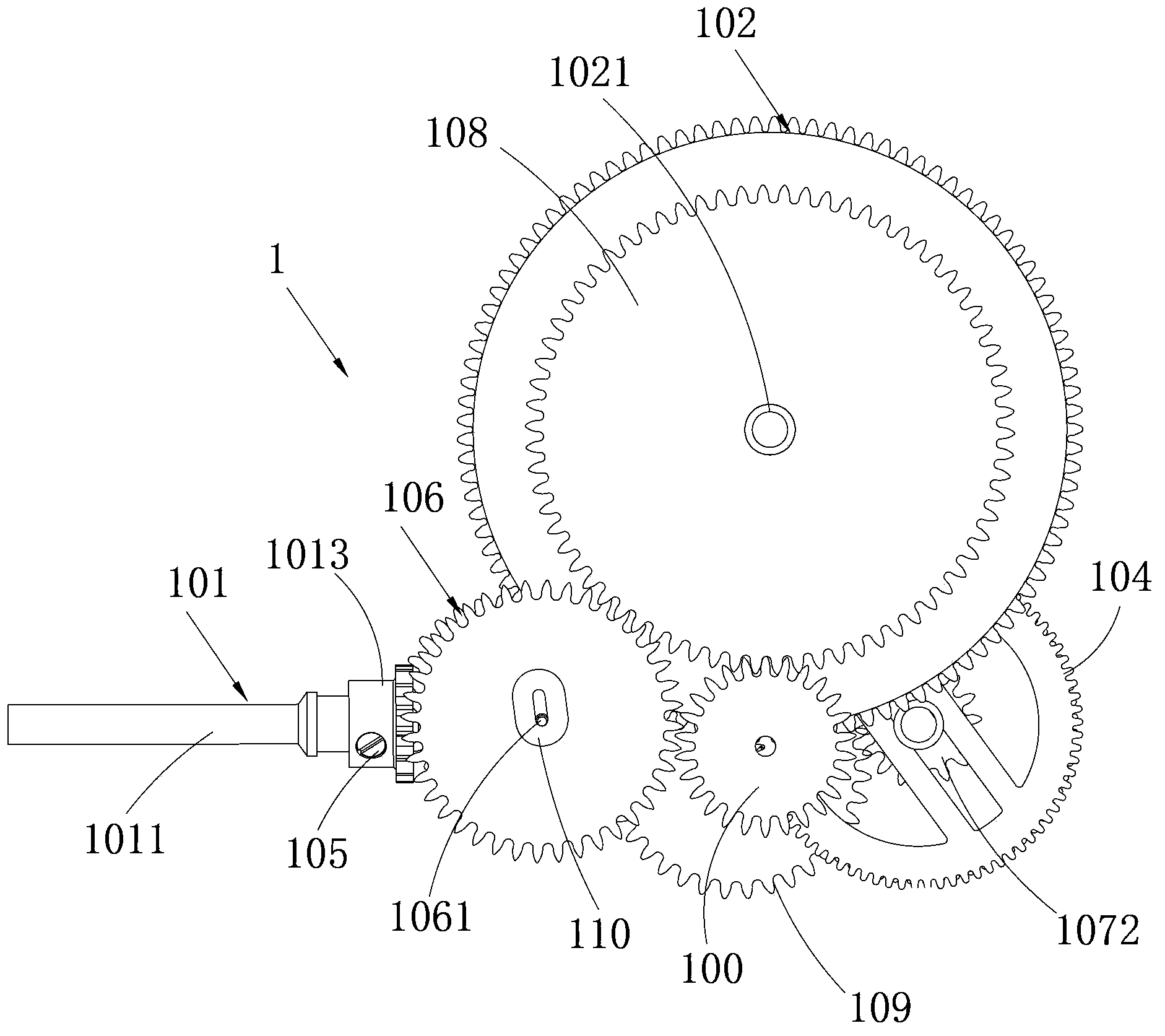
[0039] Such as Figure 5 Shown is another preferred embodiment provided by the present invention.

[0040] The difference between this embodiment and Embodiment 1 is that the first gear structure is the first reversing gear 111, and the second gear structure is the second reversing gear 112. The first reversing gear 111 includes the vertical gear 1013 and can The first lower switching gear 1112 driven to rotate by the vertical gear 1013 and the first upper switching gear 1111 placed above the first lower switching gear 1112, and when the first lower switching gear 1112 rotates forward, It can drive the first reversing upper gear 1111 to rotate. On the contrary, when the first reversing lower gear 1112 rotates in the opposite direction, the first reversing upper gear 1111 will not rotate with the first reversing lower gear 1112, that is, the first reversing lower gear 1112 will not rotate. In the disengaged state; similarly, the second reversing gear 112 includes a second reve...

Embodiment 3

[0045] Such as Figure 6 Shown is another preferred embodiment provided by the present invention.

[0046] The difference between this embodiment and Embodiments 1 and 2 is that the above-mentioned first gear structure is the first sliding gear 106 in Embodiment 1, and correspondingly, the second gear structure is the second reversing gear in Embodiment 2 gear 112. In this way, when the vertical gear 1013 rotates forward, it can drive the first sliding gear 106 to rotate, and then drive the first intermediate gear train to rotate to realize the winding operation; Rotate to the gear 112, and then drive the second intermediate gear train to rotate, thereby realizing the needle setting operation.


PUM


Abstract

The invention relates to the technical field of timekeepers and discloses a winding and setting mechanism which comprises a handle shaft, a barrel gear with a built-in spring, a minute gear and an hour gear which is sleeved on the minute gear. One end of the handle shaft is provided with a vertical gear. A first gear structure, which is driven only by the vertical gear to rotate when the vertical gear rotates in the forward direction, is arranged above the vertical gear. A second gear structure, which is driven only by the vertical gear to rotate when the vertical gear rotates in reverse, is arranged below the vertical gear. A first intermediate gear train is engaged between the first gear structure and the barrel gear. A second intermediate gear train is engaged between the second gear structure and the minute gear and the hour gear. The gears are main parts in the above mechanism. As long as the handle shaft is rotated in the forward direction or in reverse, winding or setting operation can be realized. The operation is simple, not damaging the timekeeper. In addition, the volume of the mechanism can be reduced greatly; with gear drive as the key point, the operation is reliable, flexible and highly efficient; and lifetime of the timekeeper is prolonged.

Description

technical field [0001] The invention relates to the technical field of clocks and watches, in particular to a winding needle setting mechanism and a watch including the winding needle setting mechanism. Background technique [0002] The movement of clocks and watches is equipped with a winding needle mechanism, which is used to wind the clock and adjust the time and date. [0003] The winding and setting mechanism in the movement of clocks and watches in the prior art generally adopts a rod spring structure, that is, the cooperation of rods and reeds, etc., so that the winding and setting operations can be realized after the stem is pulled. [0004] Taking domestic watches and ETA2824 watches as examples, when the arbor needs to be disassembled, when the force and distance of the pull bar are slightly larger, the bar may come out of the notch of the spring tube, or even the bar is completely tilted and turned over. Thereby separating from the arbor and losing the position-l...

Claims


Application Information

Patent Timeline
Patent Type & Authority Applications(China)
IPC IPC(8): G04B27/00G04B3/04
Inventor 曹荣林张克来
Owner TIAN WANG ELECTRONICS (SHENZHEN) CO LTD
Why Eureka
Try Eureka