Locking device

A technology of locking device and stop position, which is applied in the direction of mechanical control device, transmission device control, device for preventing/limiting/recovering the movement of parts of the control mechanism, etc. Parts fall off and other problems, to ensure the effect of setting the degree of freedom

Active Publication Date: 2014-01-15
HONDA MOTOR CO LTD
View PDF5 Cites 1 Cited by
  • Summary
  • Abstract
  • Description
  • Claims
  • Application Information

AI Technical Summary

Problems solved by technology

[0004] However, in the case of press-fitting and fixing the retainer to the support hole of the housing, it is necessary to appropriately set the dimensional difference between the inner diameter of the support hole and the outer diameter of the retainer, that is, the interference amount. If it is too large, there is a possibility that the support hole of the housing will be broken when the holder is pressed in. On the contrary, if the interference is too small, there is a possibility that the holder will fall off from the support hole of the housing after being pressed.
[0005] However, when the housing and the holder are made of materials with different thermal expansion coefficients, even if the interference is set appropriately, the housing and the holder expand or contract at different thermal expansion coefficients due to temperature changes. There is a possibility that the support hole of the housing may break or the retainer may fall off due to a change in the amount of interference
[0006] In particular, when the housing and the holder are made of different materials, the upper limit of the interference is limited by the parts on the side with a lower material strength, so the degree of freedom in setting the interference decreases. The problem

Method used


Image

  • Locking device
  • Locking device
  • Locking device

Examples


no. 2 Embodiment approach

[0032] Below, based on Figure 1 ~ Figure 3 First and second embodiments of the present invention will be described.

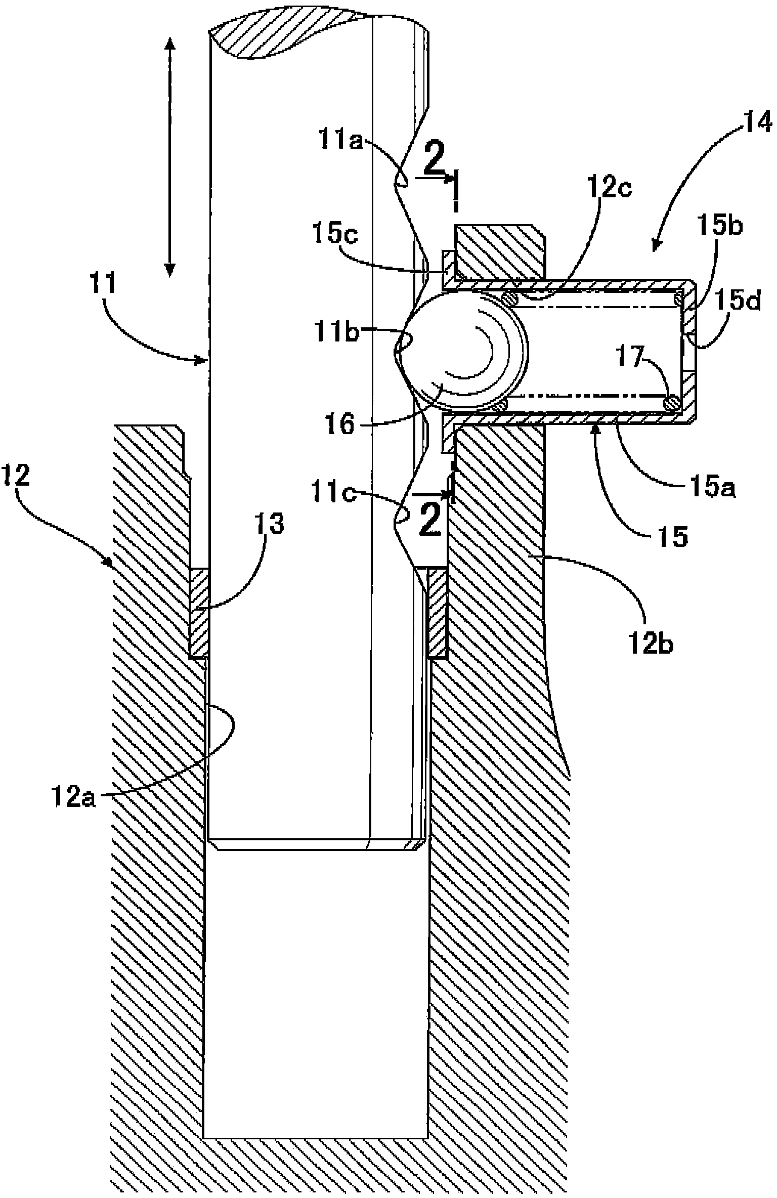
[0033] Such as figure 1 As shown, the shift fork shaft 11 supporting the shift fork of the automobile transmission is slidably supported by the bush 13, and the bush 13 is formed by pressing into the case 12 of the transmission made of an aluminum material. The guide hole 12a of the shift fork shaft 11 is connected with the shift lever or actuator operated by the driver and moves in the axial direction. For example, three V-shaped grooves 11 a , 11 b , and 11 c are separately formed at predetermined intervals in the axial direction on the outer peripheral surface of the shift fork shaft 11 .

[0034] The locking device 14 for positioning the shift fork shaft 11 at three positions in the axial direction is constituted by three members of a retainer 15 , a ball 16 and a spring 17 . The holder 15 is a member obtained by drawing a plate material made of iron, a...

no. 3 Embodiment approach

[0056] Next, based on Figure 4 A third embodiment of the present invention will be described.

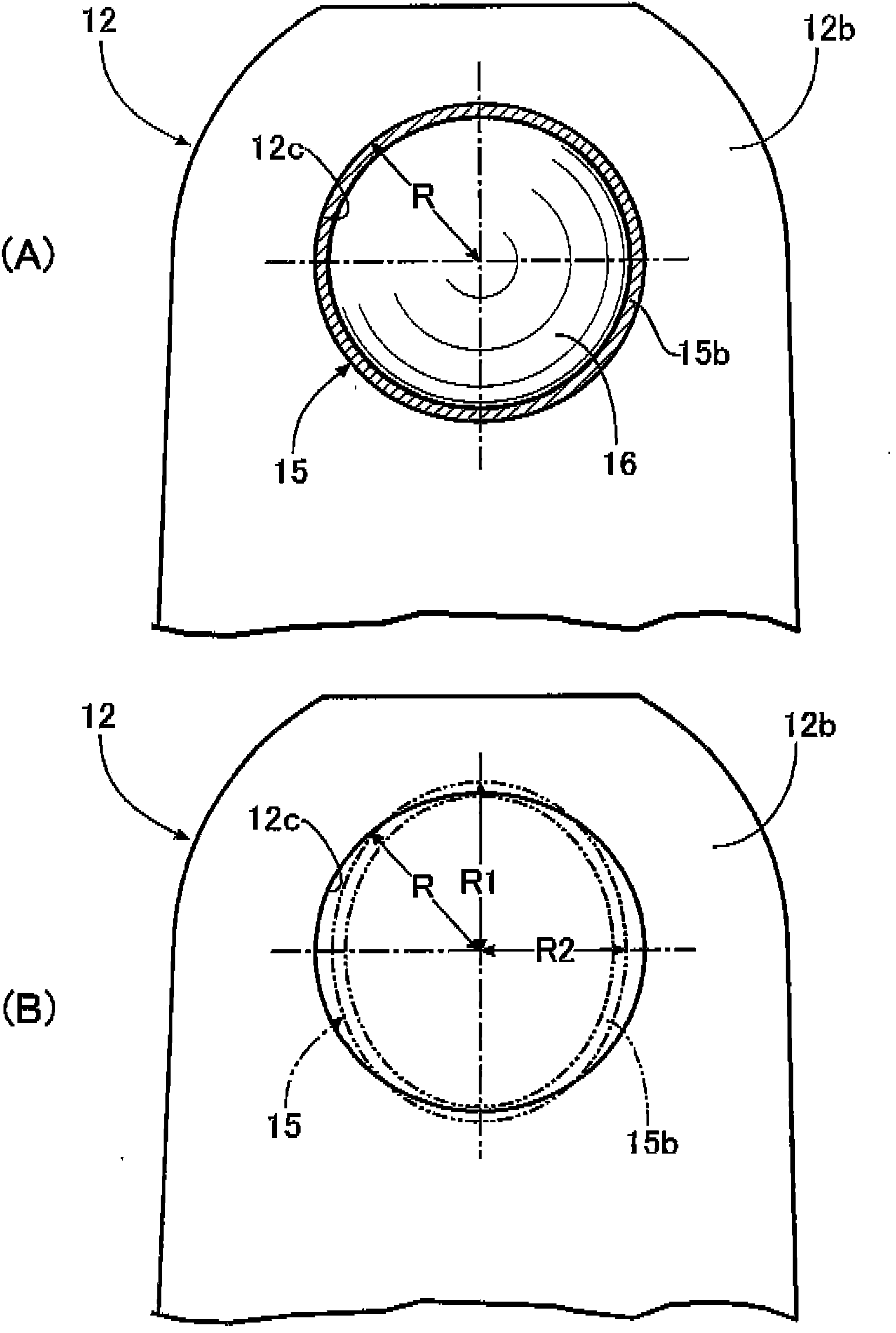
[0057] In the first and second embodiments, the cross-sectional shape of the inner peripheral surface of the support hole 12c of the housing 12 is a perfect circle, and the cross-sectional shape of the outer peripheral surface of the main body portion 15a of the holder 15 is an ellipse, but in the third embodiment In the form, the cross-sectional shape of the inner peripheral surface of the support hole 12c of the housing 12 is formed into an ellipse, and the cross-sectional shape of the outer peripheral surface of the main body portion 15a of the holder 15 is formed into a triangular shape (rice ball shape) with rounded corners. . And, when the cross-sectional shape of the inner peripheral surface of the support hole 12c and the cross-sectional shape of the outer peripheral surface of the holder 15 are overlapped in a state where their centers coincide, the cross-sectional shape ...


PUM


Abstract

The invention provides a locking device which can enable the degree of freedom of setting of the magnitude of interference between a retainer of the locking device and a support hole of a housing to be increased. When the section shape of an internal circumference surface of the support hole (12c) of the housing (12) coincides with the section shape of a peripheral surface of the retainer (15) of the locking device (14) with centers being coincident, the section shape of the inner circumference surface passes through an inner side and an outer side of the section shape of the periphery surface, thus, in the process of pressing-in, the section shape of the periphery surface of the retainer (15) deforms to adapt to the section shape of the internal circumference surface of the support hole (12c), thus proper surface pressure (stress) is generated on a pressing-in surface, and the housing (12) can be prevented from cracking and the retainer (15) can be prevented from dropping. Thus, even if the housing (12) is made of aluminium material and the retainer (15) is made of iron material and difference exists in thermal expansivity, the degree of freedom of setting of the magnitude of interference between the two can be increased.

Description

technical field [0001] The present invention relates to a locking device comprising: a support hole formed in a case; a cylindrical holder made of a material different from that of the case and pressed into the support hole; a ball , which is accommodated in the holder in a movable manner; and a spring, which is accommodated in the holder and biases the ball, by elastically abutting the ball on a shaft capable of sliding in the axial direction A plurality of grooves are formed on the shaft, thereby positioning the shaft in any one of a plurality of stop positions. Background technique [0002] According to the following patent document 1, there is known a technology in which the locking device has a cylindrical holder (sleeve), a ball and a spring, the ball is housed in the holder so as to be able to move freely, and the spring is arranged on the inside of the holder. In such a locking device, a retainer having a perfect circular cross section is press-fitted into and fixed...

Claims


Application Information

Patent Timeline
Patent Type & Authority Applications(China)
IPC IPC(8): G05G5/06F16H63/38
Inventor 小西弘顺
Owner HONDA MOTOR CO LTD
Why Eureka
Try Eureka