
Stator, motor and making method of stator

A technology for stators and motors, applied in the manufacture of motor generators, the shape/style/structure of winding insulation, electrical components, etc., can solve the problems of irregular length tension, contact, short circuit, etc.

Inactive Publication Date: 2014-01-15
SANKYO SEIKI MFG CO LTD
View PDF6 Cites 4 Cited by
  • Summary
  • Abstract
  • Description
  • Claims
  • Application Information

AI Technical Summary

Problems solved by technology

[0004] However, even in the case where the length of the transition line portion located at the threading portion is optimized by the protrusion provided on the wall surface on the side of the threading portion of the partition wall, the length of the transition line portion may sometimes be affected by the threading and winding process. The tight state of the winding line is not neat, in this case, the transition line part produces slack
As a result, there is a risk that the transition line part comes into contact with the case, etc., and thus short-circuits

Method used


Image

  • Stator, motor and making method of stator
  • Stator, motor and making method of stator
  • Stator, motor and making method of stator

Examples


Embodiment Construction

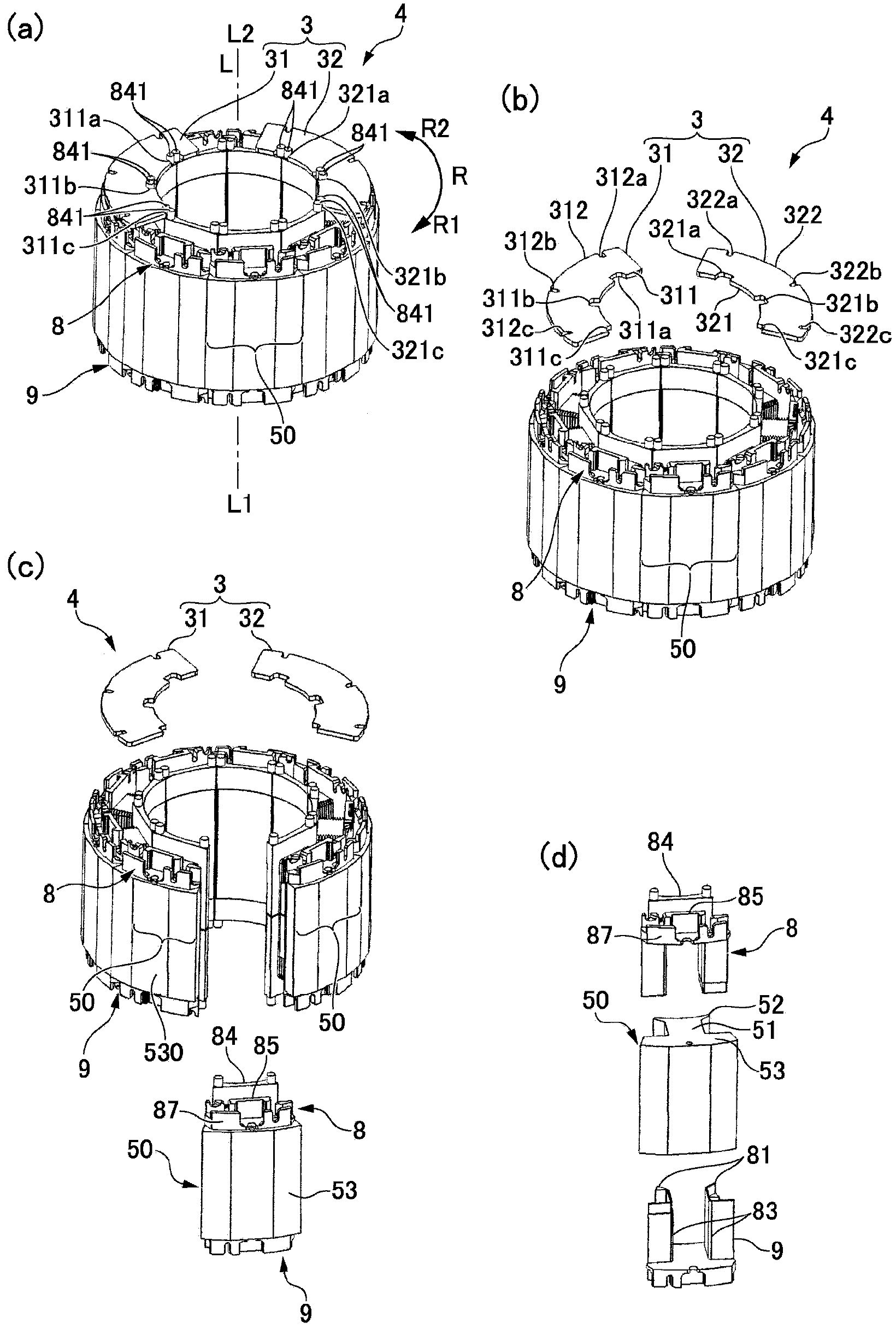
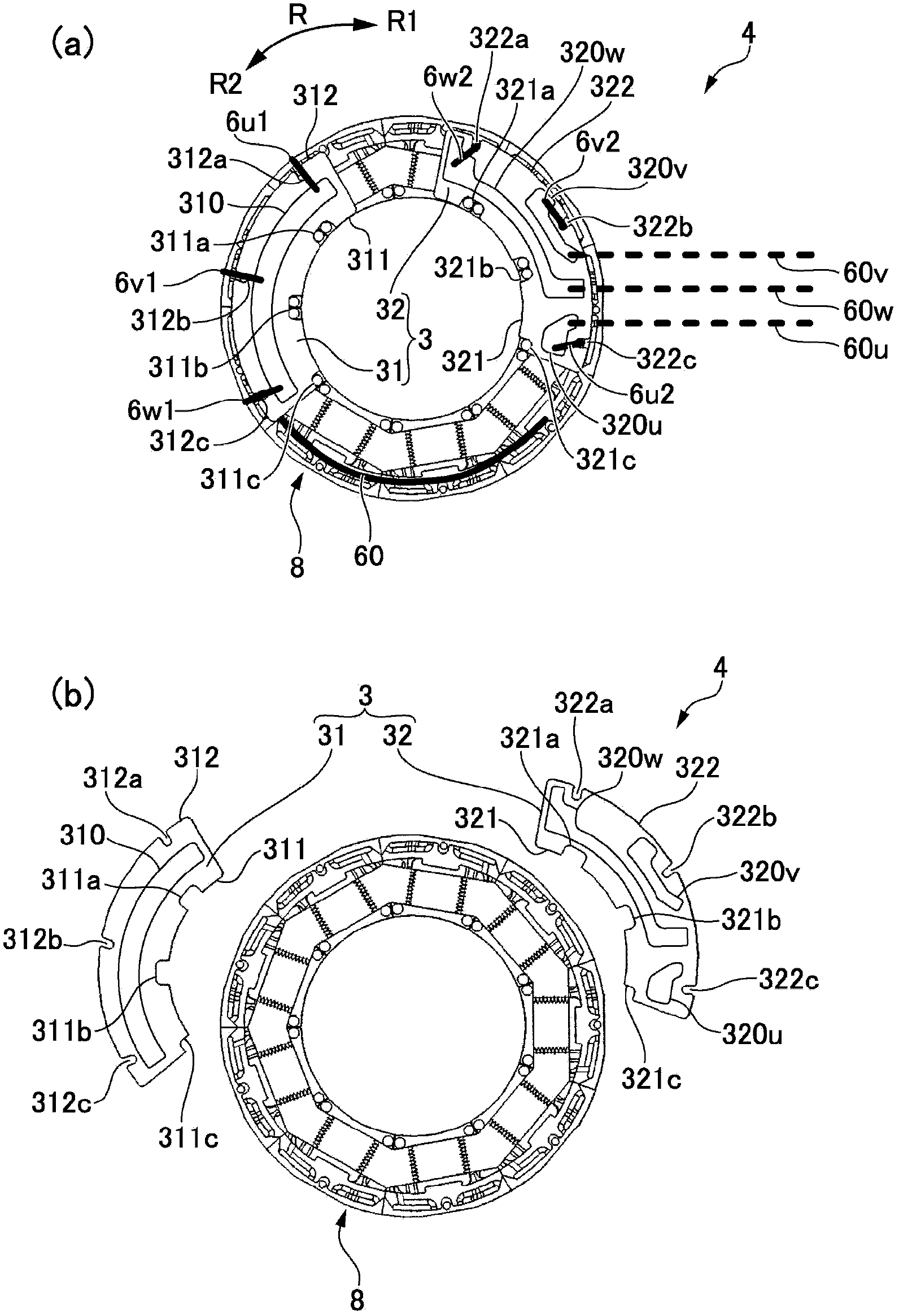
[0046] Hereinafter, an embodiment for carrying out the present invention will be described with reference to the drawings. In the following description, in the motor axial direction L, the side where the motor shaft largely protrudes is the output side L1, and the opposite side is the opposite output side L2. In addition, the circumferential direction is indicated by an arrow R, one side is R1, and the other side is R2, and it demonstrates. In addition, in the following description, the case where this invention is applied to an inner rotor type motor is mainly demonstrated.

[0047] (The overall structure of the motor)

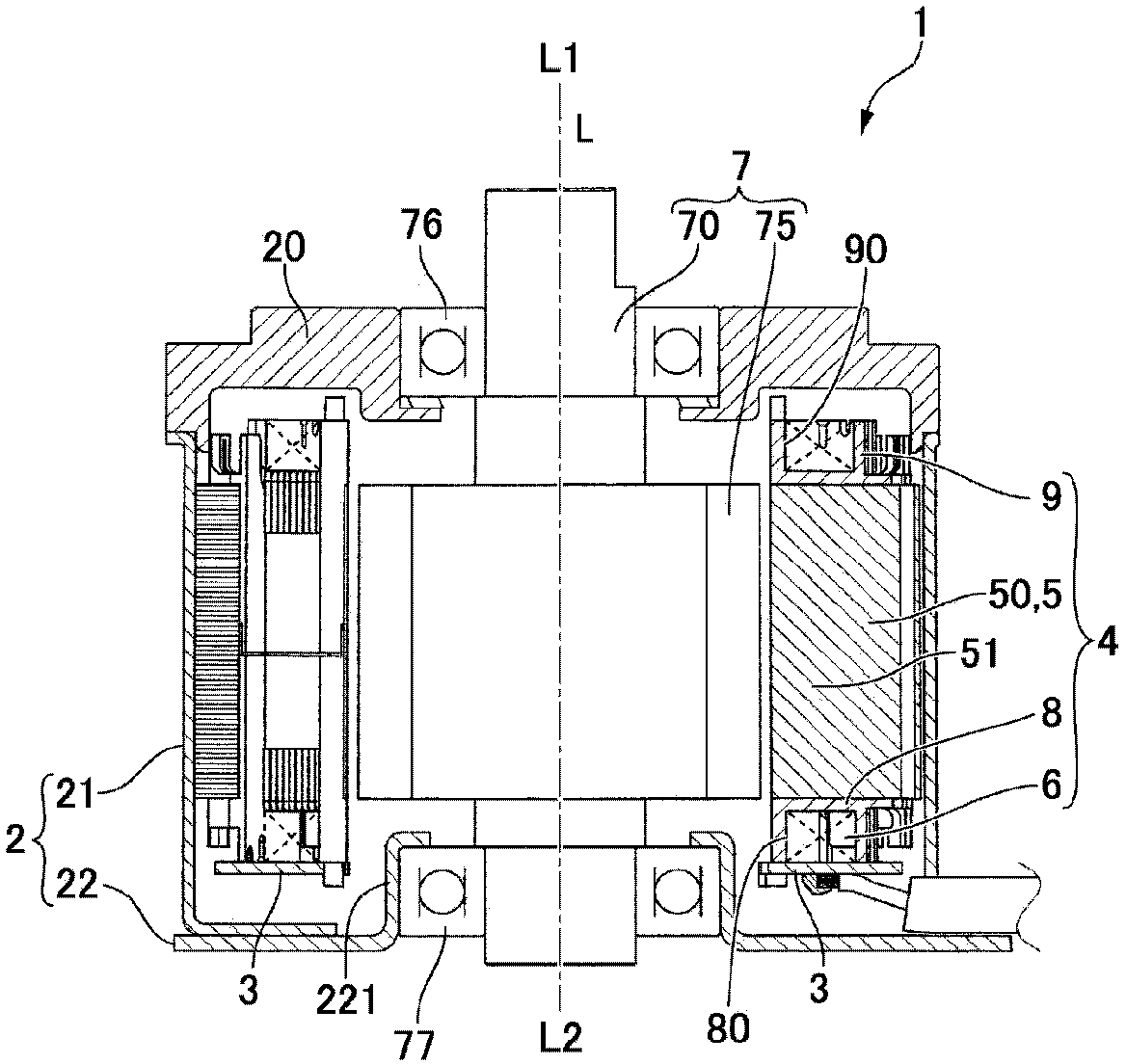
[0048] figure 1 It is a longitudinal cross-sectional view of the motor to which the present invention is applied. figure 1 The motor 1 shown is a three-phase inner rotor type direct current (DC) brushless motor, and has a bottomed cylindrical motor housing 2 whose output side L1 in the motor axial direction L is an open end, and is fixed by methods such as...


PUM


Abstract

The invention provides a stator, a motor and a making method of the stator, and the stator can adjust a transition line to a proper tensed state in a winding portion, arranged on a covering salient pole, of an insulation part. The insulation part (8) of the stator (4) is provided with the winding portion (86); the winding portion (86) is positioned in a position adjacent to a body portion (82) wrapped by a coil (6) in a radial direction; in the winding portion (86), the transition portion (60) of the coil (6) penetrates in a periphery direction. A wall surface on the winding portion (86) side of a second flange portion (85) (dividing wall) separating the body portion (82) from the winding portion (86) is provided with a recessed portion (850) recessing in a position facing the body portion (82); after the transition line portion (60) penetrates the winding portion (86), certain part (60a) of the transition line portion (60) bends towards the recessed portion (850). Therefore, the transition line portion (60) is in a properly tensed state.

Description

technical field [0001] The present invention relates to a stator in which a winding wire is wound around a salient pole with an insulating member interposed therebetween, a motor including the stator, and a method for manufacturing the stator. Background technique [0002] The following proposal has been proposed: a stator used in a motor or the like has a structure in which a winding wire is wound around a salient pole with an insulating member interposed therebetween, and the insulating member is provided with a winding portion and a partition wall, and the winding portion is in contact with the salient pole covering the structure. The main body portion is provided with the transition wire portion of the winding wire to be wound in the circumferential direction at radially adjacent positions, and the partition wall separates the main body portion from the winding portion. In addition, a convex portion protruding toward the side opposite to the position of the main body por...

Claims


Application Information

Patent Timeline
Patent Type & Authority Applications(China)
IPC IPC(8): H02K3/34H02K3/46H02K15/095
Inventor 竹村达也
Owner SANKYO SEIKI MFG CO LTD
Learn More