
Electronic equipment

A technology of electronic equipment, resistance, applied in the field of electronic equipment

Inactive Publication Date: 2014-01-15
HONG FU JIN PRECISION IND (SHENZHEN) CO LTD +1
View PDF0 Cites 0 Cited by
  • Summary
  • Abstract
  • Description
  • Claims
  • Application Information

AI Technical Summary

Problems solved by technology

However, when electronic devices switch between audio formats of different formats, plosive sounds will also be produced. Since there is no corresponding circuit control, the plosive sounds can still be heard by the user.

Method used


Image

  • Electronic equipment
  • Electronic equipment

Examples


Embodiment Construction

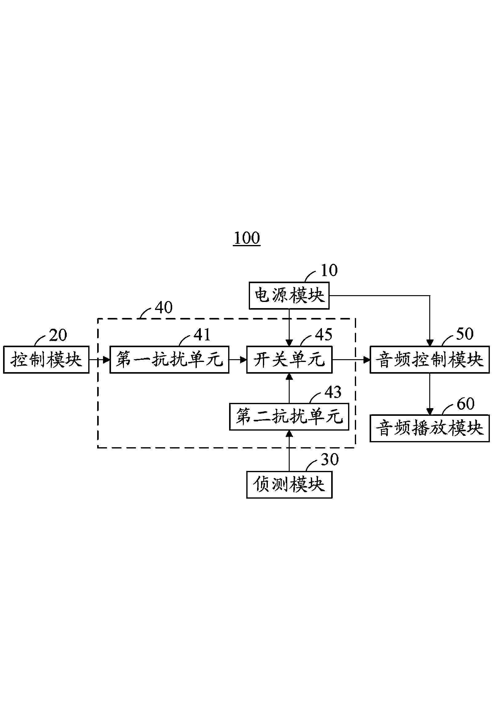
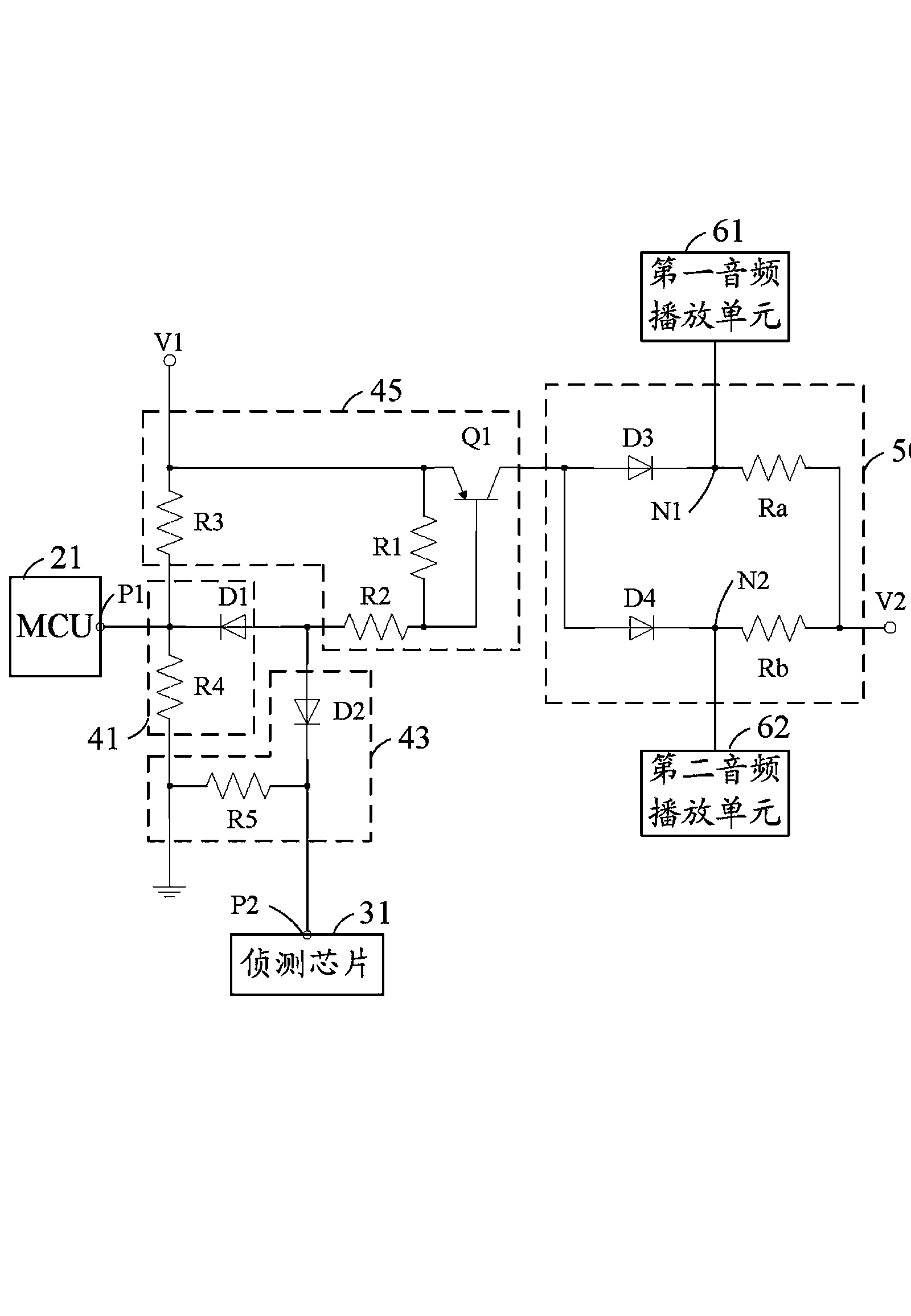
[0011] see figure 1 , which is a functional block diagram of the electronic device 100 in a preferred implementation manner. The electronic device 100 includes a power module 10 , a control module 20 , a detection module 30 , a switch module 40 , an audio control module 50 and an audio playback module 60 . The electronic device 100 is switchable between a first state and a second state. In this embodiment, the first state is the power-on state, and the second state is the power-off state.

[0012] The power supply module 10 is used to output the first supply voltage to the switch module 40 and output the second supply voltage to the audio control module 50 . In this embodiment, the first voltage is a forward voltage, and the second voltage is a negative voltage.

[0013] The control module 20 is electrically connected to the switch module 40, which is used to detect the state of the electronic device 100, and generates a first control signal when the electronic device 100 i...


PUM


Abstract

Electronic equipment can be switched between two states of power on and power off and comprises a power supply module, a control module, a detection module, a switch module, an audio control module and an audio play module. The power supply module is used for outputting a first supply voltage. The control module is electrically connected to the switch module. When the electronic equipment is switched between the power on and power off states, the control module outputs a first control signal, the switch module responses to the first control signal to be conducted, generates a first voltage according to the first supply voltage and provides the first voltage to the audio control module. The audio control module outputs a first signal according to the first voltage so as to control the audio play module to stop outputting audios. The detection module is electrically connected to the switch module and is used for outputting the first control signal to the switch module when the audio format for playing of the electronic equipment is detected and switching is carried out.

Description

technical field [0001] The invention relates to an electronic device. Background technique [0002] The electronic equipment can be switched between two states of power-on and power-off, and it includes a microcontroller and an audio playing module. When switching between the two states of power-on and power-off, the electronic device will generate a pop noise (pop noise). In the prior art, a microcontroller (Micro Control Unit, MCU) is used to control the audio playback module to power on or off the electronic device. Stops audio output when switched off, thereby eliminating plosives. However, when the electronic device switches between audio formats of different formats, plosive sounds will also be generated, and the plosive sounds can still be heard by the user because there is no corresponding circuit control. Contents of the invention [0003] In view of this, it is necessary to provide an electronic device that can eliminate plosives generated under different situa...

Claims


Application Information

Patent Timeline
Patent Type & Authority Applications(China)
IPC IPC(8): H04R3/00
CPCG11B19/02H04B15/005
Inventor 邓雪冰汪涛程海龙马晓辉林国彬李新平
Owner HONG FU JIN PRECISION IND (SHENZHEN) CO LTD
Learn More