Lost-motion variable valve actuation system with cam phaser

A technology of cam phaser and idling system, which is applied in the direction of valve driving device, machine/engine, valve lift, etc. It can solve the problems that the valve brake system cannot be fully achieved, is not enough to respond to cycle-cycle changes, and is not hard enough.

Inactive Publication Date: 2014-01-15
SKADERI GRUP LLC
View PDF14 Cites 2 Cited by
  • Summary
  • Abstract
  • Description
  • Claims
  • Application Information

AI Technical Summary

Problems solved by technology

[0061] Existing valve braking systems cannot fully meet these requirements
They are too heavy or not stiff enough to brake at the required speeds
In addition, they only offer a limited range of on or off variability and are insufficiently responsive to cycle-to-cycle changes

Method used


Image

  • Lost-motion variable valve actuation system with cam phaser
  • Lost-motion variable valve actuation system with cam phaser
  • Lost-motion variable valve actuation system with cam phaser

Examples


Embodiment Construction

[0109] Certain exemplary embodiments will now be described to provide an overall understanding of the principles of the structure, function, manufacture, and use of the devices and methods disclosed herein. One or more examples of these embodiments are illustrated in the accompanying drawings. Those skilled in the art will appreciate that the devices and methods specifically described herein and illustrated in the accompanying drawings are non-limiting exemplary embodiments and that the scope of the present invention is defined only by the claims. Features illustrated or described with respect to one example embodiment may be combined with features of other embodiments. The scope of the present invention is intended to include such modifications and variations.

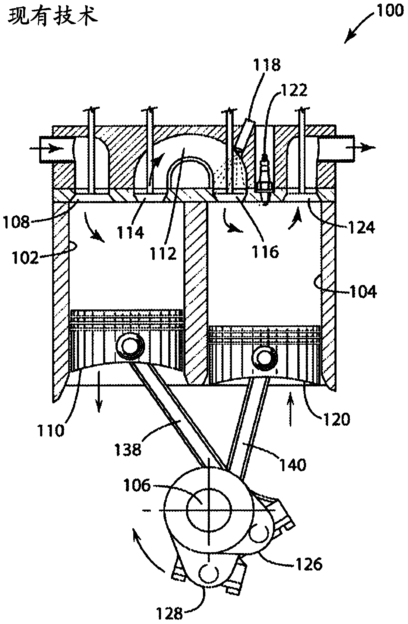
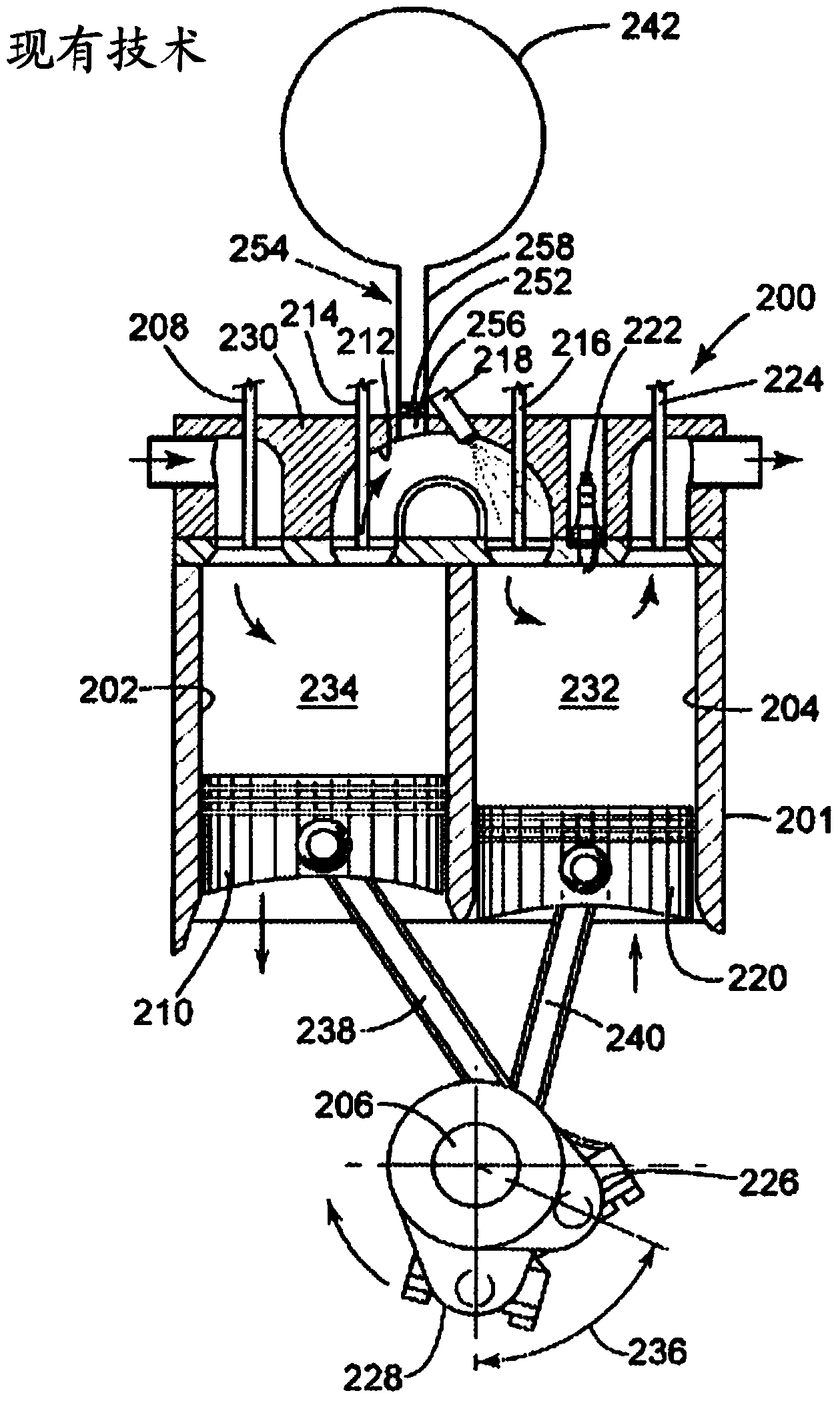
[0110] Although certain methods and apparatus are disclosed herein with respect to split-cycle engines and / or air hybrid engines, those of ordinary skill in the art will appreciate that the methods and apparatus disc...


PUM


Abstract

Devices and related methods are disclosed that generally involve variable actuation of engine valves. In one embodiment, a valve train for a split-cycle internal combustion engine or an air hybrid split-cycle engine is provided that includes a cam phaser, a dwell cam, an adjustable mechanical element for performing a variable valve actuation function, and / or a valve seating control device. The devices and methods disclosed herein also have application in conventional internal combustion engines and can actuate inwardly-opening and / or outwardly-opening valves.

Description

[0001] Exchange of references to related applications [0002] This application claims the benefit of US Provisional Patent Application No. 61 / 436,735, filed January 27, 2011, which is hereby incorporated by reference in its entirety. technical field [0003] The present invention relates to valve braking systems. More specifically, the present invention relates to split-cycle internal combustion engines having an idle variable valve braking system. Background technique [0004] Internal combustion engines typically include one or more valves for controlling air and fuel flow through the engine. Typically, these valves are actuated by mechanical cams. For example, a rotating shaft with a teardrop shaped cam lobe may be configured to impart motion to the valve either directly or through one or more intermediate elements. As the shaft rotates, the eccentric portion of the cam lobe imparts linear motion to the valve over the range of shaft rotation. [0005] To achieve opti...

Claims


Application Information

Patent Timeline
Patent Type & Authority Applications(China)
IPC IPC(8): F01L1/00
CPCF01L1/08F01L1/344F01L1/3442F01L3/22F01L13/0005F01L13/0063F01L2003/258F01L2013/0089F02B33/22
Inventor 里卡尔多·梅尔多莱西约翰·施沃雷尔约瑟夫·帕图尔佐
Owner SKADERI GRUP LLC
Why Eureka
Try Eureka