
Scissors

A scissors, cutter head technology, applied in metal processing, hand-held tools, manufacturing tools, etc., can solve the problems of large applied force and difficult cutting at the end

Inactive Publication Date: 2014-01-22
张家港市信佳塑料五金制品有限公司
View PDF6 Cites 5 Cited by
  • Summary
  • Abstract
  • Description
  • Claims
  • Application Information

AI Technical Summary

Problems solved by technology

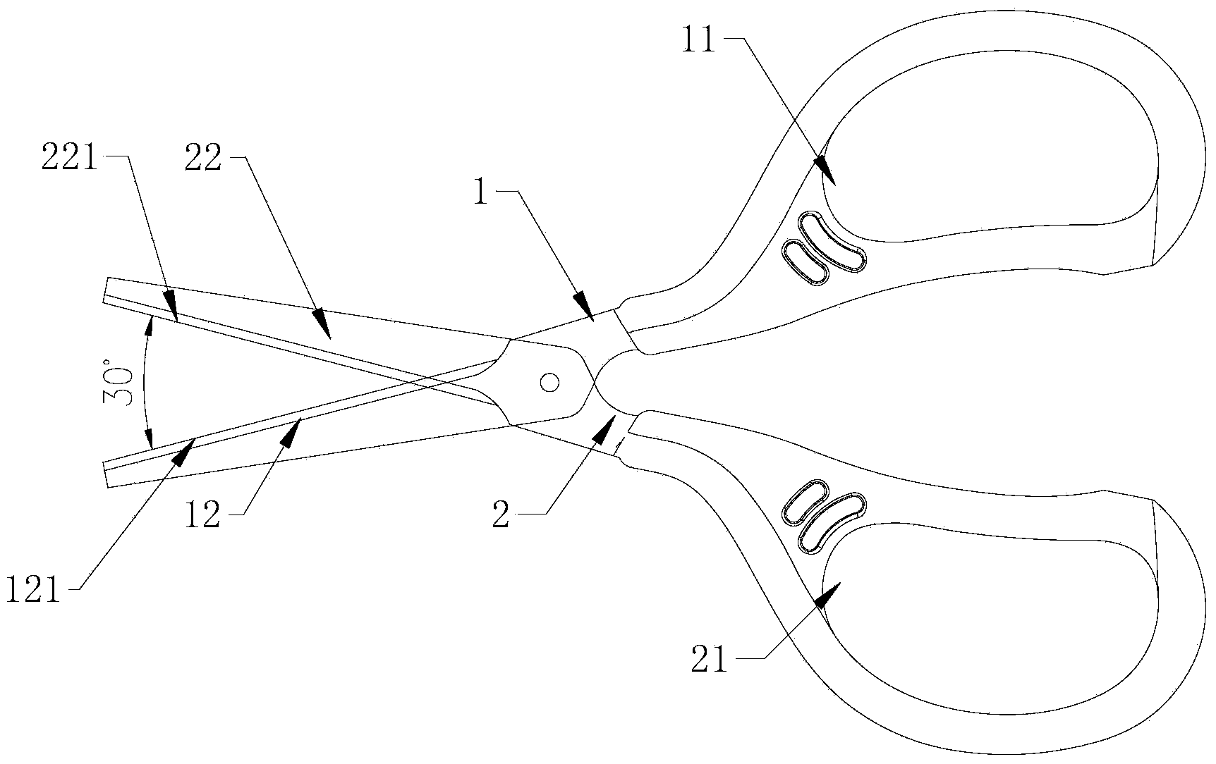
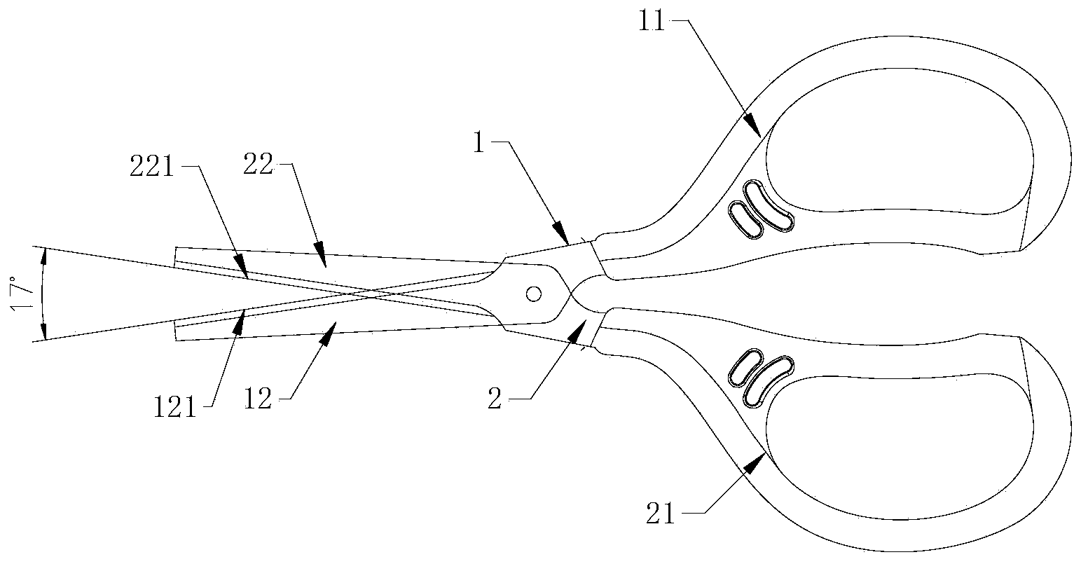
[0002] The current scissors generally include a first half body and a second half body that cooperate with each other and are hinged in the middle. The tails of the first half body and the second half body are respectively provided with a first handle and a second handle. The heads of the half body and the second half body are respectively provided with a first cutter head and a second cutter head, and the first cutter head is provided with a first cutting edge on a side adjacent to the second cutter head, and the second cutter head is further The side adjacent to the first cutter head is provided with a second cutting edge, and the first cutting edge and the second cutting edge are straight cutting edges. When cutting an object, the fingers hold the first handle and the second handle tightly so that The first cutting edge of the first cutter head and the second cutting edge of the second cutter head move closer to each other to complete the shearing, as figure 1 , figure 2 As shown, since the intersection point between the first cutting edge and the second cutting edge (that is) and the hinge point are getting farther and farther from the beginning to the end of the cutting process of the first cutter head and the second cutter head , therefore, the operator will apply more and more force during the whole process of shearing, making it very difficult to shear at the end, and the applied force will be very large

Method used


Image

  • Scissors
  • Scissors
  • Scissors

Examples


Embodiment Construction

[0017] The present invention will be described in further detail below through specific examples.

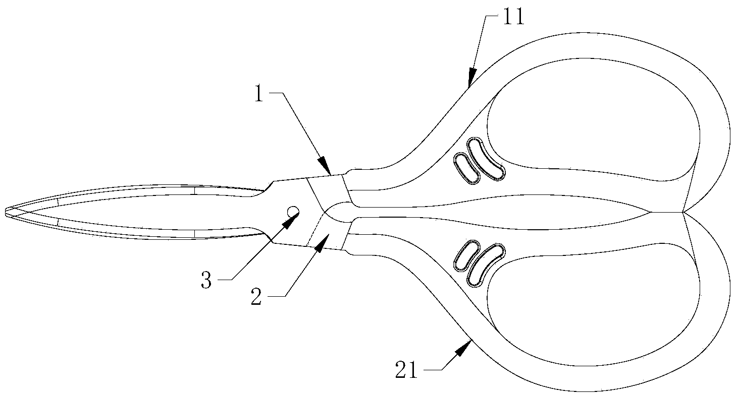
[0018] Such as figure 1 , 2 It shows a kind of scissors commonly used at present, which includes a first half body 1 and a second half body 2 that cooperate with each other and are hinged by a hinge shaft 3 in the middle, and the tails of the first half body 1 and the second half body 2 are respectively A first handle 11 and a second handle 21 are provided, and the heads of the first half body 1 and the second half body 2 are respectively provided with a first cutter head 12 and a second cutter head 22, and the first cutter head 12 is adjacent to One side of the second cutter head 22 is provided with a first cutting edge 121, and the second cutter head 22 is provided with a second cutting edge 221 on a side adjacent to the first cutter head 12. The first cutting edge 121 and the second cutting edge The mouth 221 is a straight cutting edge. Such as figure 1 As shown, in this ...


PUM


Abstract

The invention discloses a pair of scissors which is simple in structure and saves labor. The scissors comprise a first half body and a second half body which are matched mutually and hinged in the middle portions. The tail of the first half body and the tail of the second half body are provided with a first grab handle and a second grab handle respectively, and the head of the first half body and the head of the second half body are provided with a first scissor head and a second scissor head respectively. A first cutting edge is arranged on the side, close to the second scissor head, of the first scissor head, a second cutting edge is arranged on the side, close to the first scissor head, of the second scissor head, the outline of the first cutting edge and the outline of the second cutting edge are arc and arranged symmetrically, and included angles between tangent lines of all crosspoints of the first cutting edge and the second cutting edge are the same.

Description

technical field [0001] The invention relates to scissors, in particular to a labor-saving scissors. Background technique [0002] The current scissors generally include a first half body and a second half body that cooperate with each other and are hinged in the middle. The tails of the first half body and the second half body are respectively provided with a first handle and a second handle. The heads of the half body and the second half body are respectively provided with a first cutter head and a second cutter head, and the first cutter head is provided with a first cutting edge on a side adjacent to the second cutter head, and the second cutter head is further The side adjacent to the first cutter head is provided with a second cutting edge, and the first cutting edge and the second cutting edge are straight cutting edges. When cutting an object, the fingers hold the first handle and the second handle tightly so that The first cutting edge of the first cutter head and t...

Claims


Application Information

Patent Timeline
IPC IPC(8): B26B13/06B25G1/10
Inventor 汤建春
Owner 张家港市信佳塑料五金制品有限公司
Learn More