Graph printing injection molding method

A technology of injection molding and graphics, applied in the direction of coating, etc., can solve the problems of scratches, affecting the appearance, waste and environmental protection.

Inactive Publication Date: 2014-01-22
FORESHOT IND
View PDF3 Cites 1 Cited by
  • Summary
  • Abstract
  • Description
  • Claims
  • Application Information

AI Technical Summary

Problems solved by technology

[0003] However, when the above-mentioned printing operation is directly printed on the surface of the object to be printed, the printed pattern or text will appear on the surface of the object to be printed in an embossed state. Although it has a three-dimensional effect, it is often used. Abrasion, scratches or even damage lead to incomplete patterns, which will affect the overall appearance, and even if the printed matter is intact, it will still be eliminated due to pattern distortion, causing unnecessary waste and environmental protection problems
[0004] Therefore, the follow-up derives the use of pre-bonding the pattern on the surface of a workpiece before the manufacture of a finished product, and then bonding another workpiece on the surface with the pattern by bonding (such as ultrasonic bonding), so that Forming the finished product and allowing the pattern to be formed in the finished product. In this way, the pattern is like being covered in the finished product, which can completely avoid the situation of incomplete pattern caused by abrasion, scratches or even damage. , the finished product is made by bonding, except that there are obvious joint marks on the exterior shape, and its structural strength is lower than that of the one-piece finished product, which is more likely to cause the problem of disintegration of the finished product due to dropping or collision
[0005] In view of this, in order to improve the above shortcomings, the pattern can not only avoid the incomplete pattern caused by wear, scratches or even damage, but also the structural strength of the finished product itself can reduce the problem of disintegration due to dropping or collision. The inventor has accumulated many years of experience and continuous research and development, and the present invention has been produced

Method used


Image

  • Graph printing injection molding method
  • Graph printing injection molding method
  • Graph printing injection molding method

Examples


Embodiment Construction

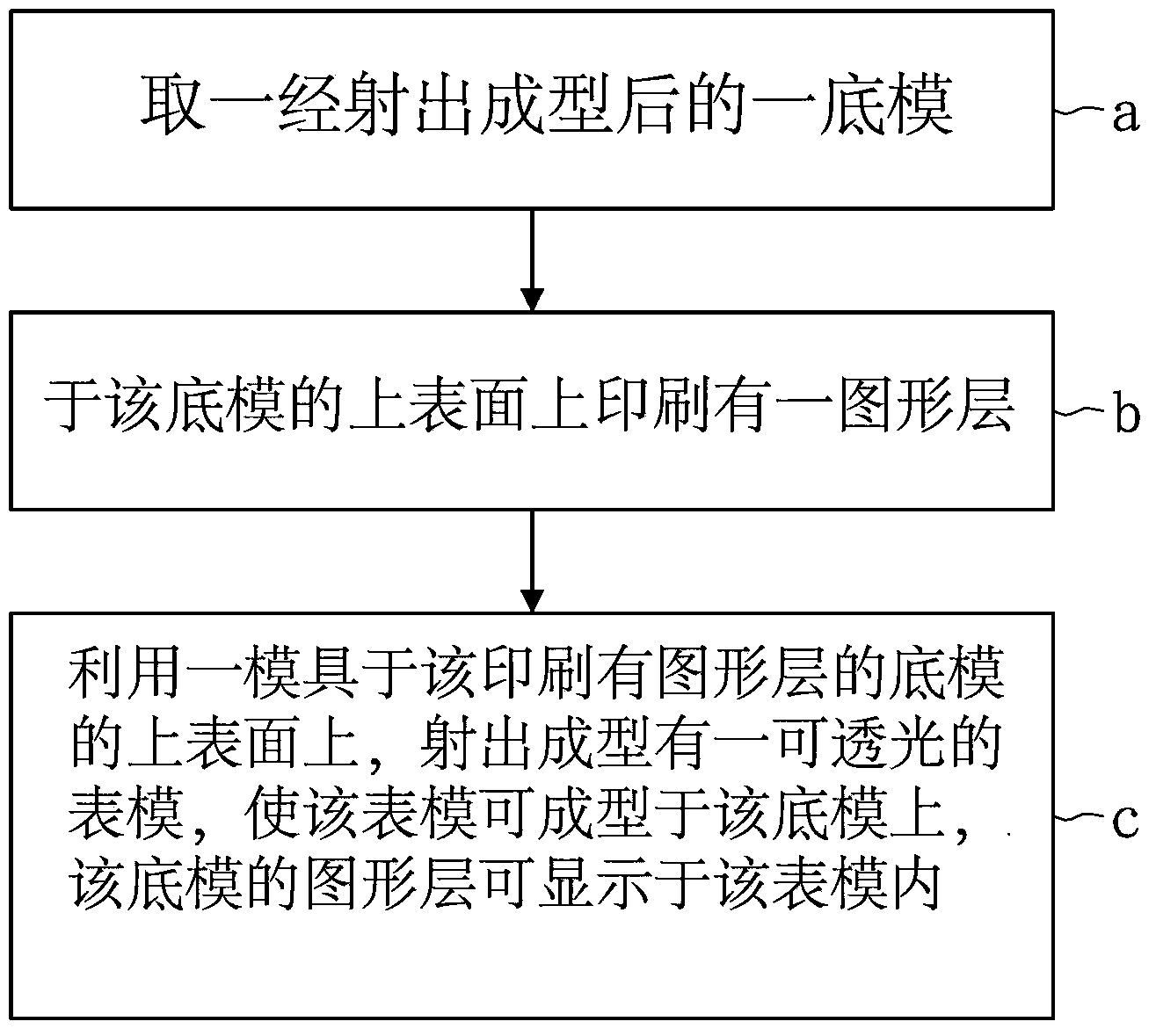
[0017] Please refer to Figures 1-3, which is an embodiment of a graphic printing injection molding method of the present invention, which includes the following steps:

[0018] Step a: Take a bottom mold 1 after injection molding;

[0019] Step b: printing a graphic layer 2 on the upper surface of the bottom mold 1;

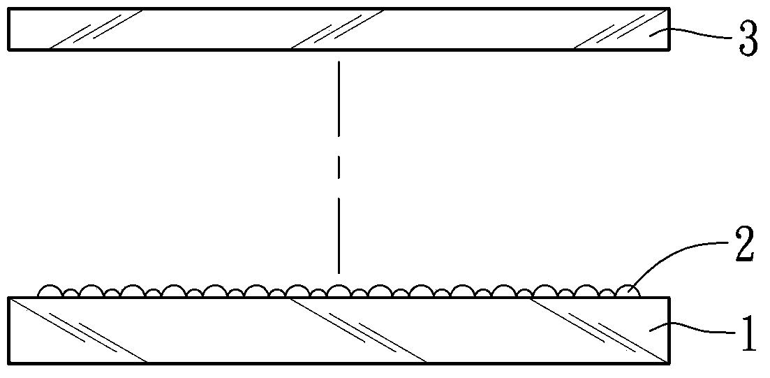
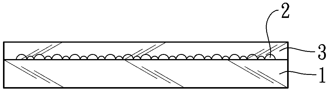
[0020] Step c: using a mold on the upper surface of the bottom mold 1 printed with the graphic layer 2, injection molding a light-permeable surface mold 3, so that the surface mold 3 can be molded on the bottom mold 1, and the bottom mold The graphic layer 2 of the mold 1 can be displayed in the surface mold 3 .

[0021] In practice, the bottom mold 1 is transparent or opaque, and the graphic layer 2 includes patterns or characters.

[0022] In this way, as shown in Figures 2 and 3, after the surface mold 3 is directly injection-molded on the bottom mold 1, a finished product can be formed, and the graphic layer 2 can pass through light as if it is wrapped in t...


PUM


Abstract

The invention provides a graph printing injection molding method. The graph printing injection molding method is characterized in that after a bottom mould formed by injection molding is taken, a graph layer is printed on the upper surface of the bottom mould; a light-transmittable surface mould is formed on the upper surface of the bottom mould printed with the graph layer by injection molding through a mould, so that the surface mould can be molded on the bottom mould and the graph layer of the bottom mould can be displayed in the surface mould.

Description

technical field [0001] The invention relates to a graphic printing injection molding method which enables the printed graphics to be molded in a model combined with two injection moldings, so that the model has high bonding strength and the graphics are not damaged. Background technique [0002] Due to the advancement of printing technology, today's printing equipment can print on the upper surface of soft materials to be printed (such as paper, cloth or other textiles) or hard materials to be printed (such as plastic, metal, glass or ceramics), making it widely used In various industrial fields, to increase the visual effect of the appearance of the product. [0003] However, when the above-mentioned printing operation is directly printed on the surface of the object to be printed, the printed pattern or text will appear on the surface of the object to be printed in an embossed state. Although it has a three-dimensional effect, it is often used. Abrasion, scratches or even...

Claims


Application Information

Patent Timeline
Patent Type & Authority Applications(China)
IPC IPC(8): B29C45/14
CPCB29C45/14688B29C2045/14696B29C2045/14713
Inventor 林铭祥
Owner FORESHOT IND
Why Eureka
Try Eureka